Shampoo filling system
A filling system and shampoo technology, which is applied in the direction of filling device cleaning, packaging, bottle filling, etc., and can solve the problems of not being able to clean the filling nozzle
- Summary
- Abstract
- Description
- Claims
- Application Information
AI Technical Summary
Problems solved by technology
Method used
Image
Examples
specific Embodiment approach 1
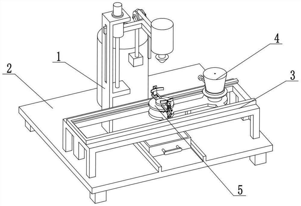
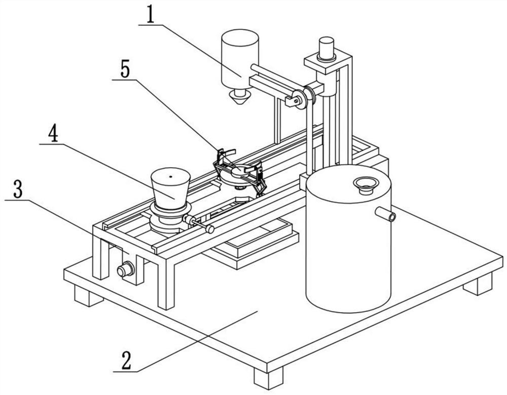
[0024] The present embodiment will be described below in conjunction with the drawings. The present invention relates to the technical field of shampoo filling, more specifically a shampoo filling system, including a lifting filling mechanism 1, a collecting chassis mechanism 2, and an inlet and outlet slideway mechanism 3 , Rotating wiping mechanism 4 and bottle body clamping mechanism 5, described bottle body clamping mechanism 5 is connected on the feeding and discharging slideway mechanism 3, and feeding and discharging slideway mechanism 3 is connected on the collection bottom frame mechanism 2, lifting and filling Mechanism 1 is connected to collecting bottom frame mechanism 2, rotating wiping mechanism 4 is connected to feeding and discharging slideway mechanism 3, and rotating wiping mechanism 4 is meshed with lifting filling mechanism 1 for transmission.
[0025] Place the shampoo bottle on the bottle body clamping mechanism 5, the in-out material slideway mechanism 3 ...
specific Embodiment approach 2
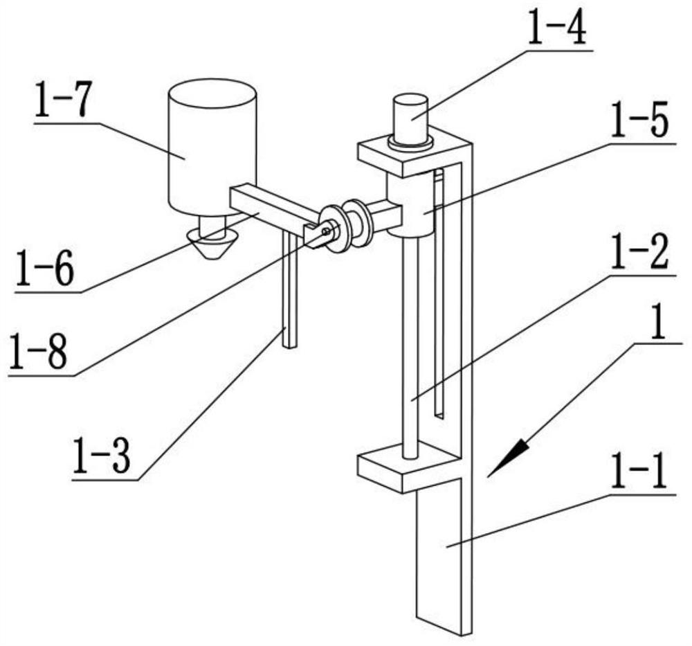
[0027] This embodiment will be described below in conjunction with the drawings. This embodiment will further explain Embodiment 1. The lifting filling mechanism 1 includes a support column 1-1, a lifting screw 1-2, a vertical rack 1-3, a vertical Motor 1-4, lifting threaded sleeve 1-5, suspension right-angle beam 1-6, filling gun 1-7 and follow-up concave wheel 1-8, follow-up concave wheel 1-8 is rotatably connected to suspension right-angle beam 1-6 The rear end, the left end of the suspension right-angle beam 1-6 is fixedly connected on the lifting threaded sleeve 1-5, the lifting threaded sleeve 1-5 is threaded on the lifting screw rod 1-2, and the lifting screw rod 1-2 is connected in rotation On the support column 1-1, the top of the lifting screw 1-2 is fixedly connected to the output shaft of the vertical motor 1-4, and the vertical motor 1-4 is fixedly connected to the top of the support column 1-1, and the vertical rack The top of 1-3 is fixedly connected to the bott...
specific Embodiment approach 3
[0030] The present embodiment will be described below in conjunction with the drawings. This embodiment will further illustrate the second embodiment. The support column 1-1 is provided with a slide hole, and the slide hole is used to match the left end of the lifting threaded sleeve 1-5 with the support. Column 1-1 sliding contact.
[0031] The left end of the lifting threaded sleeve 1-5 is slidably connected in the sliding hole on the supporting column 1-1, so as to prevent the lifting threaded sleeve 1-5 from rotating with the rotation of the lifting screw rod 1-2, so that the lifting threaded sleeve 1-5 is supported Lift up and down on the column 1-1.
PUM
 Abstract
Description
Claims
Application Information
 - R&D
- Intellectual Property
- Life Sciences
- Materials
- Tech Scout
- Unparalleled Data Quality
- Higher Quality Content
- 60% Fewer Hallucinations
Browse by: Latest US Patents, China's latest patents, Technical Efficacy Thesaurus, Application Domain, Technology Topic, Popular Technical Reports.
© 2025 PatSnap. All rights reserved.Legal|Privacy policy|Modern Slavery Act Transparency Statement|Sitemap|About US| Contact US: help@patsnap.com


