Electrical camshaft adjuster and method for producing camshaft adjuster

A camshaft adjuster, camshaft adjustment technology, applied in camshaft drive, valve details, machine/engine, etc., can solve problems such as high consumption

Pending Publication Date: 2021-05-25
SCHAEFFLER TECH AG & CO KG
View PDF7 Cites 0 Cited by
  • Summary
  • Abstract
  • Description
  • Claims
  • Application Information

AI Technical Summary

Problems solved by technology

[0004] The problem with camshaft adjusters is that additional connecting elements such as centering bolts, laser structures at the seam in the screw connection, parts that have to be connected to the camshaft are required, as well as a screwing process at the customer's site. Camshaft end pieces, so establishing the connection between the electrical camshaft adjuster and the camshaft is complex
Furthermore, the conventional connection between the camshaft and the camshaft adjuster causes stresses in the driven ring gear and requires additional installation space in the transmission, for example for the adjustment shaft of the transmission. Bolt head of the centering bolt radially inside the ring

Method used


Image

  • Electrical camshaft adjuster and method for producing camshaft adjuster
  • Electrical camshaft adjuster and method for producing camshaft adjuster
  • Electrical camshaft adjuster and method for producing camshaft adjuster

Examples


Embodiment Construction

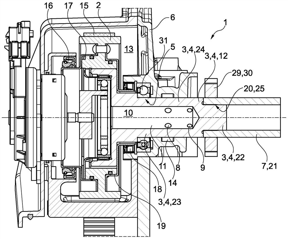
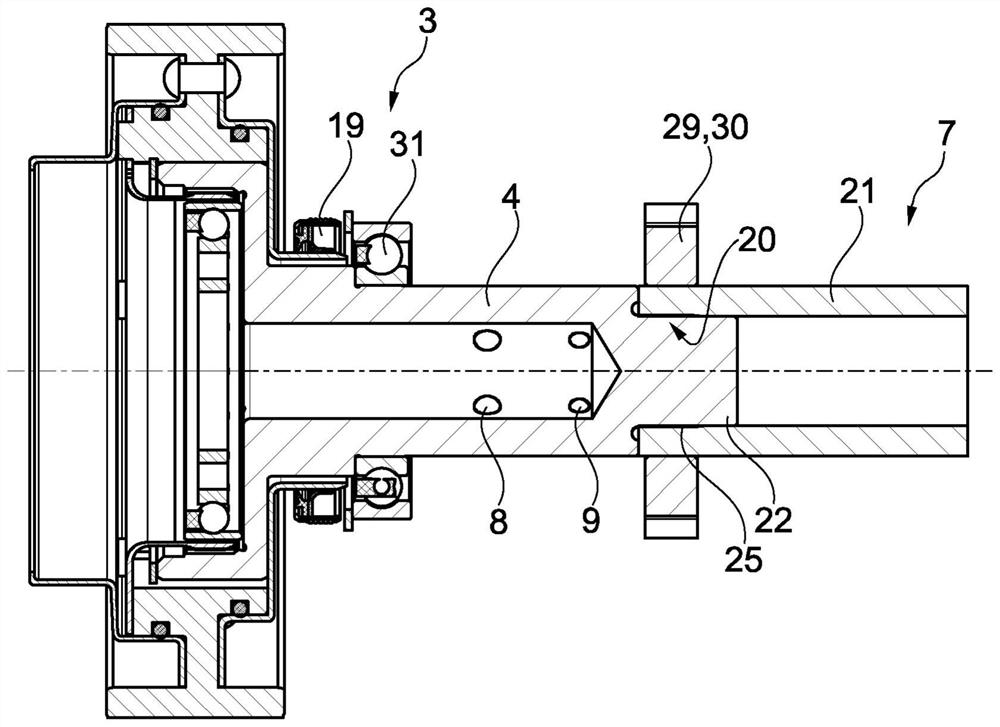
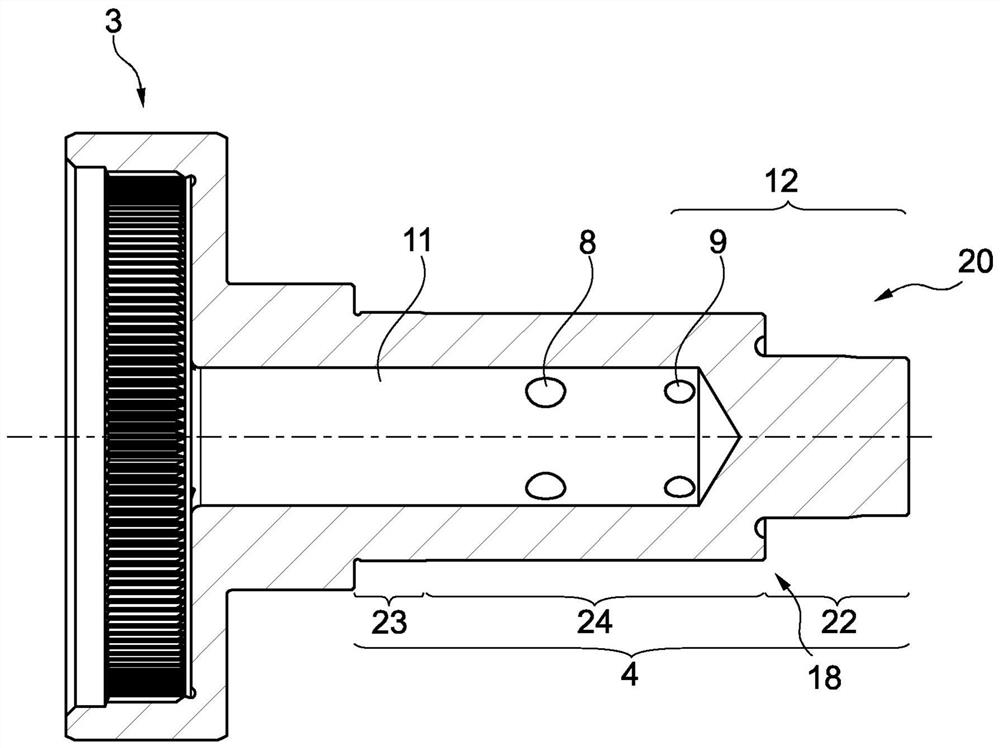
[0040] figure 1 and figure 2 An electrical camshaft adjuster 1 according to the invention for a drive train of a motor vehicle is shown. The camshaft adjuster 1 has a drive wheel 2 . The drive wheel 2 can be driven by a circulating traction mechanism. The drive wheel 2 is connected to a not shown crankshaft. The camshaft adjuster 1 has a driven ring gear 3 arranged coaxially to the drive wheel 2 . The driven ring gear 3 can rotate relative to the driving wheel 2 through the electric motor. The driven ring gear 3 has an extension 4 extending it axially. Bearing points 5 for radial support on the housing 6 are formed on the extension 4 . The extension 4 is prepared for fastening at the camshaft 7 . Preferably, the extension 4 has a higher material strength than the camshaft 7 .

[0041] According to the invention, the extension 4 has at least one at least partially radially oriented oil inlet channel 8 and at least one at least partially radially oriented oil outlet cha...


PUM


Abstract

The invention relates to an electric camshaft adjuster (1) for a drive train of a motor vehicle and to a method for producing the camshaft adjuster (1). The camshaft adjuster comprises a drive wheel (2) which can be driven by a circulating traction mechanism and a driven hollow wheel (3) which is arranged coaxially to the drive wheel (2) and which can be rotated relative to the drive wheel (2) by means of an electric motor, the driven hollow wheel (3) having an extension (4) which axially extends the driven hollow wheel (3), the extension has a bearing point (5) for radial support on the housing (6) and is intended for fastening to the camshaft (7), the extension (4) having a support (20) on the outer surface thereof for supporting the camshaft (7).

Description

technical field [0001] The invention relates to an electric camshaft adjuster for a drive train of a motor vehicle. Camshaft adjusters are used to adjust the phase of the camshaft relative to the crankshaft. The camshaft adjuster has a drive wheel that can be driven by a recirculating traction mechanism and a driven ring gear that is arranged coaxially with the drive wheel and that can be rotated relative to the drive wheel by an electric motor. The driven ring gear has an axially elongated extension which has bearing points for radial support on the housing and is intended for fastening to the camshaft. Background technique [0002] Electrical camshaft adjusters usually have: a stator housing / drive wheel that is rotatably coupled to the crankshaft, a driven ring gear that is rotatably coupled to the camshaft and can rotate relative to the drive wheel, and a driven ring gear for controlling the driven ring gear. Electrical adjustment device that rotates relative to the dri...

Claims


Application Information

Patent Timeline
Patent Type & Authority Applications(China)
IPC IPC(8): F01L1/344F01L1/348
CPCF01L1/344F01L1/348F01L1/352F01L2250/04F01L2001/34479F01L1/024F01L2820/032F01L2810/02F01L2001/3521F01L1/053F01L2250/02F01L2001/0476F01L2820/041F01L2001/0475F01L2303/00
Inventor 于尔根·韦伯雷纳·奥特尔巴赫
Owner SCHAEFFLER TECH AG & CO KG
Why Eureka
Try Eureka