Rotatable pluggable terminal block

A terminal block and male head technology, which is applied in the field of rotatable plug-in terminal blocks, can solve the problems that the terminal blocks are not easy to install, difficult to disassemble and maintain, and achieve the effects of avoiding dust and moisture, facilitating maintenance, and ensuring firmness

Inactive Publication Date: 2021-05-25
SCED ELECTRONICS CO LTD
View PDF7 Cites 0 Cited by
  • Summary
  • Abstract
  • Description
  • Claims
  • Application Information

AI Technical Summary

Problems solved by technology

[0003] In order to ensure a better waterproof and dustproof effect, the terminal blocks in the prior art are generally integrated into a sealed box body. The terminal block of this structure is not only difficult to install in a small space, but also difficult to install when a fault occurs. Disassembly and maintenance

Method used


Image

  • Rotatable pluggable terminal block
  • Rotatable pluggable terminal block
  • Rotatable pluggable terminal block

Examples


Embodiment 1

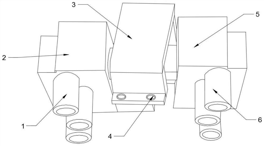
[0021] see figure 1 with figure 2 , in Embodiment 1 of the present invention, a rotatable plug-in terminal block, which includes: a male head 2, a female head 5, and a cover 3; one end of the male head 2 is provided with a terminal 7 and a mounting plate 9, and the installation A mounting hole 8 is opened on the plate 9; a wiring barrel 10 and a cover plate 11 are installed at one end of the female connector 5; when the male connector 2 and the female connector 5 are assembled to form a complete rotatable plug-in terminal block, the male connector 2 After the terminal 7 provided at one end is rotated and inserted into the terminal barrel 10 installed at one end of the female connector 5, the cover 3 is provided to cover the connection position between the terminal post 7 and the terminal barrel 10; the cover 3 is installed and fixed by the locking assembly 4 Inside the mounting hole 8 provided on the mounting plate 9;

[0022] The provided cover 3 can seal and shield the co...

Embodiment 2

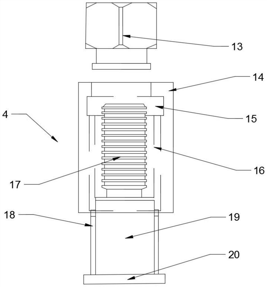
[0025] see image 3 Further, the locking assembly 4 includes a locking end 13, a movable cylinder 14 and a locking column 19, one end of the locking column 19 is provided with a stopper 20, and the other end of the locking column 19 is movably installed on the movable cylinder 14 inside, the locking column 19 is provided with a threaded section 17 on the part inside the movable cylinder 14; the internal thread of the locking end 13 is provided with the surface of the threaded section 17;

[0026] Specifically, a block 15 is provided inside the movable cylinder 14, and chute 16 is provided on both sides of the inner wall of the movable cylinder 14; protrusions 18 are provided on both sides of the locking column 19;

[0027] When the locking assembly 4 is used to connect the cover 3, the male head 2 and the female head 5 at the same time, one end of the locking post 19 provided with the threaded section 17 passes through the mounting hole 8 on the mounting plate 9 and the lower ...


PUM


Abstract

The invention relates to the technical field of terminal blocks, in particular to a rotatable pluggable terminal block which comprises a male head, a female head and a sealing cover. One end of the male head is provided with a binding post and a mounting plate, and the mounting plate is provided with a mounting hole; one end of the female head is provided with a wiring cylinder and a cover plate; when the male head and the female head are assembled to form the complete rotatable pluggable terminal block, after the binding post arranged at one end of the male head is rotatably inserted into the wiring cylinder installed at one end of the female head, the arranged sealing cover shields the connection position of the binding post and the wiring cylinder; the sealing cover is fixedly mounted in a mounting hole formed in the mounting plate through a locking assembly; according to the rotatable pluggable terminal block, a sealing and shielding effect can be achieved on the connection position of the male head and the female head through the arranged sealing cover; the locking assembly not only can ensure the firmness of the installed sealing cover, but also can facilitate the disassembly of the male head and the female head, and can achieve the timely maintenance when the whole rotatable pluggable terminal block breaks down.

Description

technical field [0001] The invention relates to the technical field of terminal blocks, in particular to a rotatable plug-in terminal block. Background technique [0002] Terminal block, common Chinese aliases include terminal board, terminal box, terminal board, terminal block, terminal block and terminal block, etc. It is one of the most special members of the connector family, and it has almost been separated from the connector at present. And become another product system independently. [0003] In order to ensure a better waterproof and dustproof effect, the terminal blocks in the prior art are generally integrated into a sealed box body. The terminal block of this structure is not only difficult to install in a small space, but also difficult to install when a fault occurs. Disassembly and maintenance. [0004] In view of the problems in the background technology above, the present invention aims to provide a rotatable plug-in terminal block. Contents of the invent...

Claims


Application Information

Patent Timeline
Patent Type & Authority Applications(China)
IPC IPC(8): H01R9/24
CPCH01R9/24
Inventor 王南
Owner SCED ELECTRONICS CO LTD
Why Eureka
Try Eureka