Rotary-type sugar crop vaporizing device

A vaporization device and rotary technology, applied in confectionery, confectionery industry, chemical instruments and methods, etc., can solve problems such as uneven heating, uneven heating of sugar material, easy leakage of sugar material heating, etc., and shorten the processing cycle , reduce energy consumption, good support effect

Active Publication Date: 2012-09-26
DUJIANGYAN TIANWANG FOOD IND
View PDF4 Cites 6 Cited by
  • Summary
  • Abstract
  • Description
  • Claims
  • Application Information

AI Technical Summary

Problems solved by technology

Although the above-mentioned patented technical solution has largely solved the problem of uneven heating of the sugar material, it still exists: the problem of uneven heating of the sugar material has not been completely solved; the fluidity of the sugar material during the heating process is not good, resulting in uneven heating; The sugar material is easy to leak during the heating process, etc.

Method used


Image

  • Rotary-type sugar crop vaporizing device
  • Rotary-type sugar crop vaporizing device
  • Rotary-type sugar crop vaporizing device

Examples


Embodiment 1

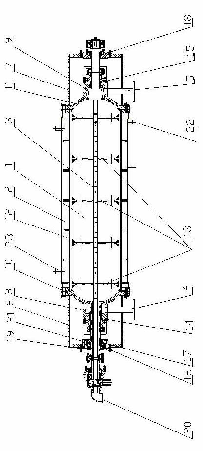
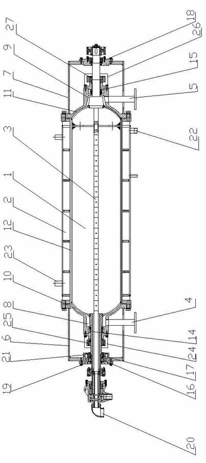
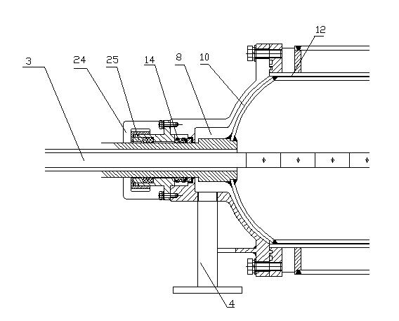
[0027] The rotary sugar vaporization device includes an inner cylinder 1, an outer cylinder 2, a driving device, a main shaft 3, a sugar inlet 4 and a sugar outlet 5 arranged on the outer cylinder 2, and the main shaft 3 runs through the inner cylinder 1 and the outer cylinder 2 Connected with the driving device and drives the inner cylinder 1 to rotate, the inner cylinder 1 is located in the outer cylinder 2, forming the first annular gap 8, the second annular gap 10, the third annular gap 12, the fourth annular gap 11 and the fifth annular gap 9 , the spacing of the first annular gap 8, the second annular gap 10 and the third annular gap 12 decreases in turn, the spacing of the fourth annular gap 11 and the second annular gap 10 is the same, the fifth annular gap 9 and the second annular gap The spacing of the gaps 8 is the same.

Embodiment 2

[0029] The rotary sugar vaporization device includes an inner cylinder 1, an outer cylinder 2, a driving device, a main shaft 3, a sugar inlet 4 and a sugar outlet 5 arranged on the outer cylinder 2, and the main shaft 3 runs through the inner cylinder 1 and the outer cylinder 2 Connected with the driving device and drives the inner cylinder 1 to rotate, the inner cylinder 1 is located in the outer cylinder 2, forming the first annular gap 8, the second annular gap 10, the third annular gap 12, the fourth annular gap 11 and the fifth annular gap 9 , the spacing of the first annular gap 8, the second annular gap 10 and the third annular gap 12 decreases in turn, the spacing of the fourth annular gap 11 and the second annular gap 10 is the same, the fifth annular gap 9 and the second annular gap The spacing of the gaps 8 is the same. The pitch of the third annular gap 12 is 1.4mm.

Embodiment 3

[0031] The rotary sugar vaporization device includes an inner cylinder 1, an outer cylinder 2, a driving device, a main shaft 3, a sugar inlet 4 and a sugar outlet 5 arranged on the outer cylinder 2, and the main shaft 3 runs through the inner cylinder 1 and the outer cylinder 2 Connected with the driving device and drives the inner cylinder 1 to rotate, the inner cylinder 1 is located in the outer cylinder 2, forming the first annular gap 8, the second annular gap 10, the third annular gap 12, the fourth annular gap 11 and the fifth annular gap 9 , the spacing of the first annular gap 8, the second annular gap 10 and the third annular gap 12 decreases in turn, the spacing of the fourth annular gap 11 and the second annular gap 10 is the same, the fifth annular gap 9 and the second annular gap The spacing of the gaps 8 is the same. The pitch of the third annular gap 12 is 1.5mm. The main shaft 3 is a hollow cylinder, and a section of the main shaft located in the inner cylind...


PUM


Abstract

The invention discloses a rotary-type sugar crop vaporizing device, and belongs to a device for concentrating liquid sugar crops in the industry of industrial or food processing. The rotary-type sugar crop vaporizing device mainly comprises an inner cylinder and an outer cylinder; sugar crops are heated by utilizing the clearance between the inner cylinder and the outer cylinder, thus the sugar crops in the clearance are heated and vaporized rapidly so as to achieve the aims of dehydration. The rotary-type sugar crop vaporizing device provided by the invention has the advantages that the vaporizing effect is obvious, the sugar crops are heated uniformly, and the sugar crops can not be leaked.

Description

technical field [0001] The invention discloses a rotary sugar vaporization device, which belongs to a device for concentrating liquid sugar in industry or food processing industry. Background technique [0002] At present, most methods of concentrating sugar materials are concentrated at room temperature, concentrated under reduced pressure, thin film evaporation, rotary evaporation, etc. These methods repeatedly heat the liquid sugar materials that need to be concentrated for a long time, and the heating is uneven, which not only consumes a lot of energy , Also lead to the unstable quality of the sugar material after concentration, so that the quality of the product is reduced. [0003] Subsequently, the patent No. 200420105827.0 appeared, the application date was December 30, 2004, the disclosure date was February 1, 2006, and the invention name was the patent technical scheme of the rotary ultra-thin film vacuum concentrator. The technical solution of this patent is: ado...

Claims


Application Information

Patent Timeline
Patent Type & Authority Applications(China)
IPC IPC(8): B01D1/00A23G3/02
Inventor 罗明秀王润华
Owner DUJIANGYAN TIANWANG FOOD IND
Why Eureka
Try Eureka