Supercharge Your Innovation With Domain-Expert AI Agents!

Laser obstacle removing device

An obstacle-removing device and laser technology, applied in the direction of machine/support, overhead line/cable equipment, supporting machine, etc., can solve the problems of easy failure, easy deviation, existence of errors, etc., to improve safety, extend distance, The effect of turning and moving easily

Active Publication Date: 2021-05-25
FOSHAN POWER SUPPLY BUREAU GUANGDONG POWER GRID
View PDF17 Cites 0 Cited by
  • Summary
  • Abstract
  • Description
  • Claims
  • Application Information

AI Technical Summary

Problems solved by technology

Although the laser emitter of this patent can rotate around two vertical directions, only the laser emitter is installed on the base of the tripod, and the upper part of the laser emitter is provided with a collimator. The laser and the collimator are not located on the same straight line, which is prone to deviation , and the patent uses an electric push rod to control the laser transmitter to rotate up and down, which is prone to failure and errors
The aiming device of the existing laser emitter has been displayed by a display, and the aiming situation is displayed on the screen of the display. If the display is installed on the top of the laser emitter, the above-mentioned problems will also exist.

Method used

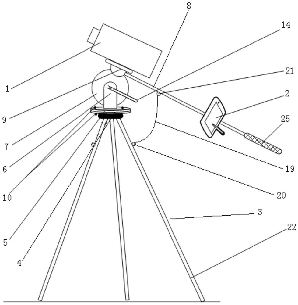
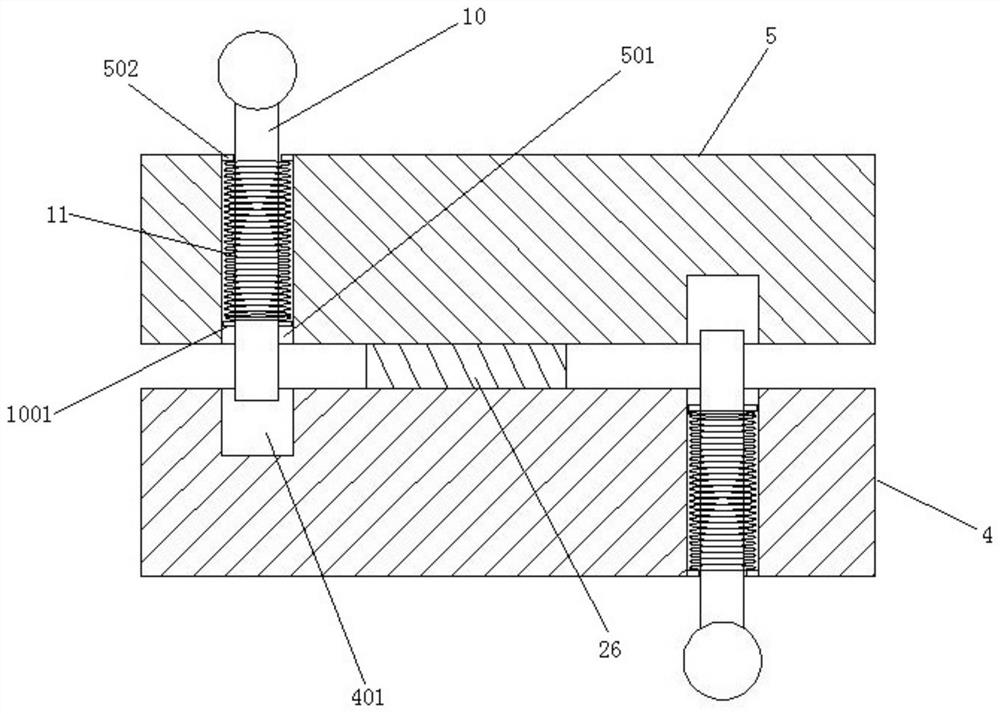
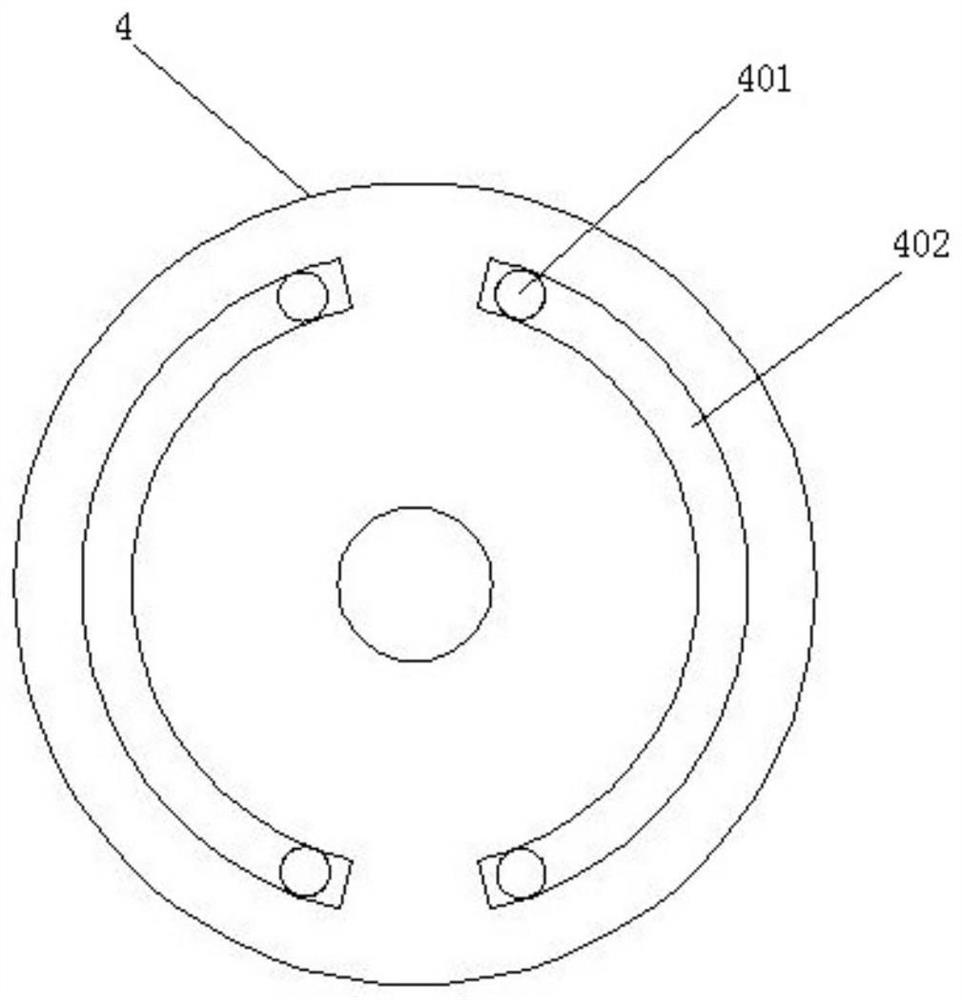

Image

  • Laser obstacle removing device
  • Laser obstacle removing device
  • Laser obstacle removing device

Examples


Embodiment Construction

[0024]DETAILED DESCRIPTION OF THE PREFERRED EMBODIMENTS The following examples are intended to illustrate the invention, but are not intended to limit the scope of the invention.

[0025]In the description of the present invention, it is to be noted that the terms "center", "longitudinal", "horizontal", "upper", "lower", "front", "post", "left", "right", " The orientation or location relationship of the indicated by "bottom" "" horizontal "," top "," bottom "," outside ", etc. is based on the orientation or positional relationship shown in the drawings, is only for ease of describing the invention and simplification. Description, rather than indicating or implying that the device or element must have a specific orientation, constructing and operating in a particular orientation, and thus is not to be construed as limiting the invention. Moreover, the term "first", "second", "third" is only used to describe purposes, and cannot be understood as an indication or implies relative importan...


PUM


Abstract

The invention relates to the technical field of power transmission line maintenance, and discloses a laser obstacle removing device which comprises a laser transmitter, a displayer, a supporting frame, a bearing platform, a working platform, a mounting plate, a rotating wheel and an operating rod, wherein the bearing platform is connected to the top end of the supporting frame, the working platform is rotatably connected to the bearing platform in the vertical direction, and the mounting plate is connected to the working platform; the rotating wheel is rotatably connected to the mounting plate in the horizontal direction, a support is arranged on the rotating wheel, the laser transmitter is connected to the support, the operating rod is a straight rod, one end of the operating rod is connected with the support, a support is arranged on the operating rod, and the displayer is connected to the support, so that the laser transmitter and the displayer are located on the same straight line, and a user can align and aim at conveniently. According to the obstacle clearing device, the obstacle clearing accuracy is improved, the mechanisms are all of mechanical structures, errors caused by motor failure or error accumulation can be prevented, the distance between a user and the laser transmitter can be prolonged through the operating rod, the effect of prolonging the force arm is achieved, and the laser transmitter can be easily rotated and moved.

Description

Technical field[0001]The present invention relates to the field of transmission line maintenance techniques, and more particularly to a laser cleavage device.Background technique[0002]The safe operation of high voltage transmission lines is in the grid and its importance. In recent years, the construction of power grids has been rapidly developed, and the transmission line can be seen everywhere. At special times such as wind, migratory birds, the ground light objects are easy to fall on the transmission line, and the safety operation of the transmission line is seriously harmful in moist weather. At the same time, a laser cleaner that cleans the high-altitude-sea-hanging-hanging-hanging laser starts in multi-regional power grid. It uses high-power laser to burn out, which can be convenient for the cleverwork. However, the laser detergent power is large, and the existing directional control platform and the insurance device uses a more advanced electronic electric control method, bu...

Claims


Application Information

Patent Timeline
Patent Type & Authority Applications(China)
IPC IPC(8): H02G1/02F16M11/04F16M11/08F16M11/18
CPCH02G1/02F16M11/04F16M11/08F16M11/18
Inventor 韩春雨陈国辉陈志成李洪涛夏晓斌施志民陈涛洪黎顺泰谭远就刘汉强冼世平覃加范
Owner FOSHAN POWER SUPPLY BUREAU GUANGDONG POWER GRID
Features
  • R&D
  • Intellectual Property
  • Life Sciences
  • Materials
  • Tech Scout
  • Unparalleled Data Quality
  • Higher Quality Content
  • 60% Fewer Hallucinations
Learn More