
Distributed energy supply operation system, forming method and device thereof and terminal equipment

An operating system and distributed technology, applied in the direction of energy storage, circuit devices, single-network parallel feeding arrangement, etc., can solve the problems of users in the region, the increase of power system load, and the unstable operation of the power system, etc., to achieve The effect of avoiding grid burden, saving resources, and balancing power supply

Pending Publication Date: 2021-05-25
POWER DISPATCHING CONTROL CENT OF GUANGDONG POWER GRID CO LTD
View PDF7 Cites 2 Cited by
  • Summary
  • Abstract
  • Description
  • Claims
  • Application Information

AI Technical Summary

Problems solved by technology

[0003] The embodiment of the present invention provides a distributed energy supply operation system and its formation method, device and terminal equipment, which are used to solve the problem of simultaneous start-up and operation of air-conditioning clusters in a certain area to control the increase in the load of the power system in this area. Technical problems that will cause the power system to fail to operate stably and cause trouble for users in the region

Method used


Image

  • Distributed energy supply operation system, forming method and device thereof and terminal equipment
  • Distributed energy supply operation system, forming method and device thereof and terminal equipment
  • Distributed energy supply operation system, forming method and device thereof and terminal equipment

Examples


Embodiment 1

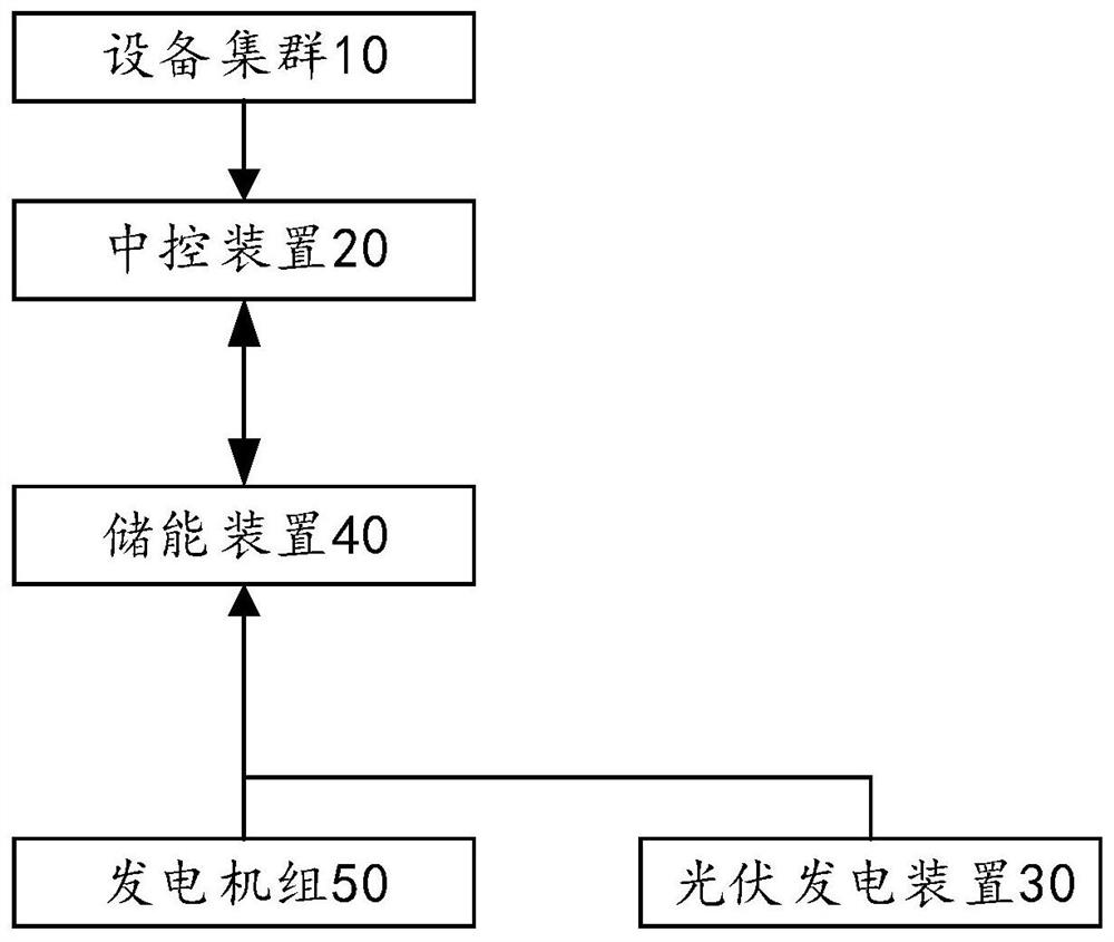
[0036] figure 1 This is a frame diagram of the distributed energy supply operation system according to the embodiment of the present invention.

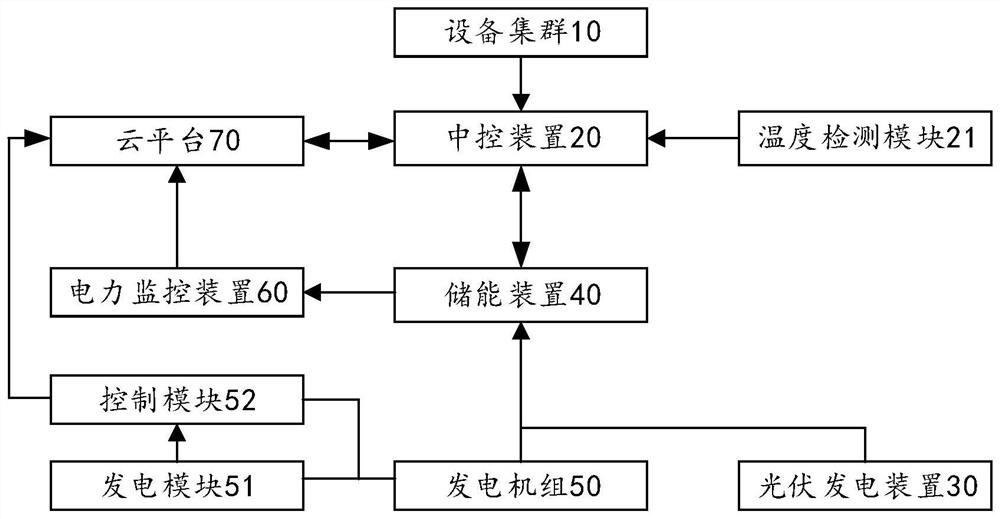
[0037] like figure 1 As shown, the embodiment of the present invention provides a distributed energy supply operation system, including an equipment cluster 10, a central control device 20, a photovoltaic power generation device 30, an energy storage device 40, and a generator set 50. The equipment cluster 10 is respectively connected with the central control device. 20 is connected to the power grid, and the generator set 50, the photovoltaic power generation device 30 and the central control device 20 are all connected to the energy storage device 40;

[0038] The central control device 20 is used to control the operation of the equipment cluster 10 and collect the operation parameters of the equipment cluster 10;

[0039] The photovoltaic power generation device 30 is used to provide electric energy and transmit the electric ene...

Embodiment 2

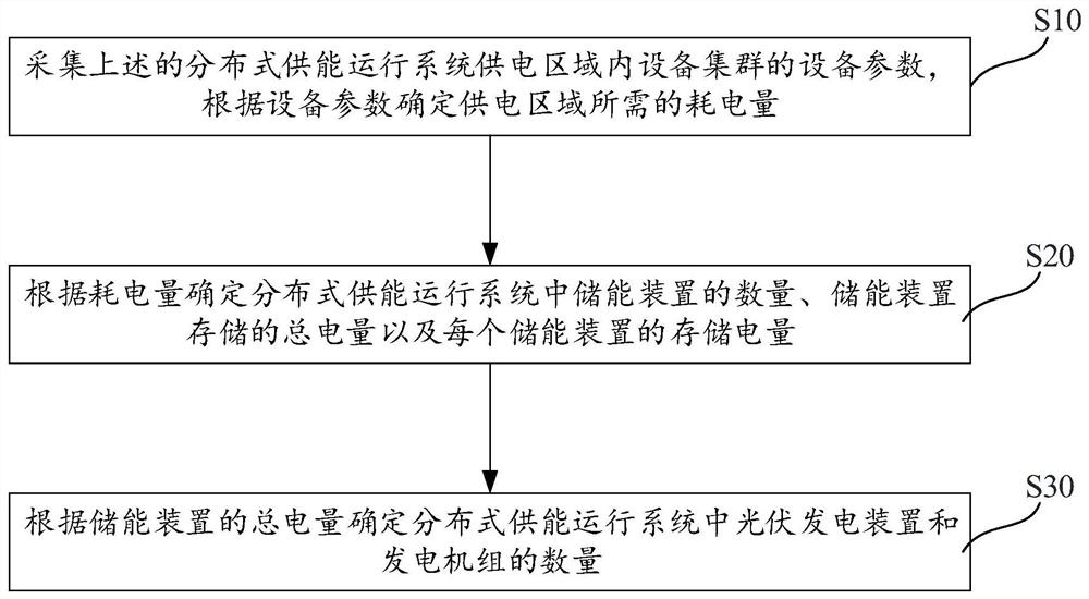
[0058] image 3 It is a flow chart of the steps of the method for forming a distributed energy supply operation system according to the embodiment of the present invention.

[0059] like image 3 As shown, an embodiment of the present invention also provides a method for forming a distributed energy supply operation system, including the following steps:

[0060] S10. Collect the device parameters of the device cluster in the power supply area of ​​the above-mentioned distributed energy supply operation system, and determine the power consumption required by the power supply area according to the device parameters;

[0061] S20. Determine the number of energy storage devices in the distributed energy supply operation system, the total power stored by the energy storage devices, and the stored power of each energy storage device according to the power consumption;

[0062] S30. Determine the number of photovoltaic power generation devices and generator sets in the distributed...

Embodiment 3

[0069] An embodiment of the present invention further provides a device for forming a distributed energy supply operation system, including a collection module, a first determination module and a second determination module;

[0070] The acquisition module is used to collect the device parameters of the device cluster in the power supply area of ​​the above-mentioned distributed energy supply operation system, and determine the power consumption required by the power supply area according to the device parameters;

[0071] a first determining module, configured to determine, according to the power consumption, the number of energy storage devices in the distributed energy supply operation system, the total power stored by the energy storage devices, and the stored power of each energy storage device;

[0072] The second determination module is configured to determine the number of photovoltaic power generation devices and generator sets in the distributed energy supply operatio...


PUM


Abstract

The embodiment of the invention relates to a distributed energy supply operation system, a forming method and device thereof and terminal equipment. The distributed energy supply operation system comprises an equipment cluster, a central control device, a photovoltaic power generation device, an energy storage device and a generator set, the equipment cluster is connected with the central control device and a power grid, and the generator set, the photovoltaic power generation device and the central control device are all connected with the energy storage device. Power is supplied through the photovoltaic power generation device and the generator set, distributed energy production is achieved, the problem that the load of a power grid is increased due to centralized power supply of the power grid is solved, and the energy storage device is adopted to store electric energy provided by the photovoltaic power generation device and the generator set so as to improve the stability of electric energy input in the energy storage device. And when the electric equipment of the equipment cluster consumes energy, the generator set is driven to generate power to provide electric energy, so that energy is recycled, resources are saved, and the problem that the power utilization of users in the region is troubled due to the fact that the power system cannot stably operate due to the fact that the air conditioner clusters in a certain region are simultaneously started to operate and the load of the power system is increased is solved.

Description

technical field [0001] The present invention relates to the technical field of distributed energy supply, and in particular, to a distributed energy supply operation system and its formation method, device and terminal device. Background technique [0002] In recent years, with the development of science and technology, the load of users' use of electricity has increased rapidly. A large number of power equipment connected to the power grid and activated at the same time have brought a very heavy burden to the power grid, and also brought a greater burden to the stable and economic operation of the power grid. Impact. In recent years, with the gradual warming of the weather, people use more and more air conditioners. In summer, whether it is shopping malls, homes, or offices, it is necessary to activate cooling equipment such as air conditioners for a long time to reduce the indoor temperature. For example, when the air-conditioning cluster in a certain area (shopping mall,...

Claims


Application Information

Patent Timeline
Patent Type & Authority Applications(China)
IPC IPC(8): H02J3/32H02J3/46
CPCH02J3/32H02J3/466Y02E70/30Y02E10/56
Inventor 杜斌曾凯文段秦尉刘嘉宁林斌
Owner POWER DISPATCHING CONTROL CENT OF GUANGDONG POWER GRID CO LTD
Learn More