High-precision scale synchronous falling type thread rolling equipment

A blanking, high-precision technology, applied in the direction of threaded products, metal processing equipment, manufacturing tools, etc., can solve the problems of automatic blanking, inaccurate thread rolling precision, etc., to achieve the goal of improving accuracy and speeding up efficiency Effect

Pending Publication Date: 2021-05-28
孙航军
View PDF11 Cites 3 Cited by
  • Summary
  • Abstract
  • Description
  • Claims
  • Application Information

AI Technical Summary

Problems solved by technology

[0006] The present invention aims at the above-mentioned defects existing in the prior art, and proposes a high-precision scale synchronous blanking type thread rolling equipment, which solves the problem that the traditional thread rolling process cannot be automatically blanked after the processing is completed, and the thread rolling The problem of inaccurate precision

Method used


Image

  • High-precision scale synchronous falling type thread rolling equipment
  • High-precision scale synchronous falling type thread rolling equipment
  • High-precision scale synchronous falling type thread rolling equipment

Examples


Embodiment 1

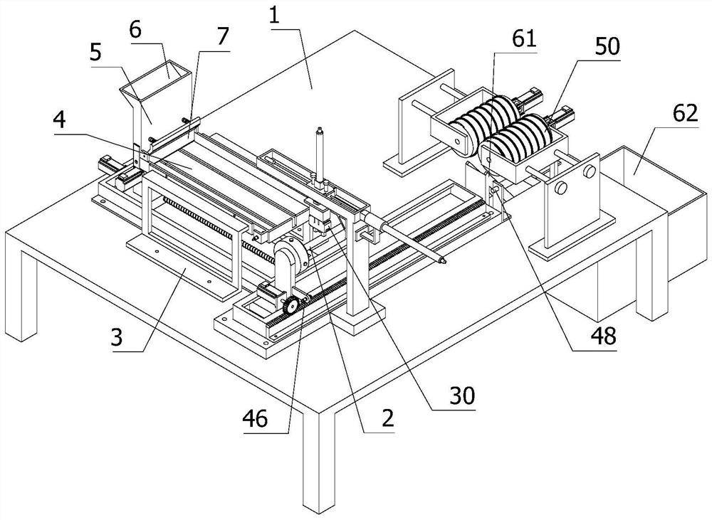
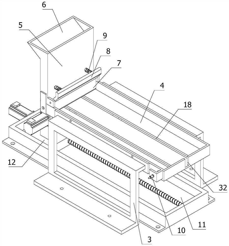
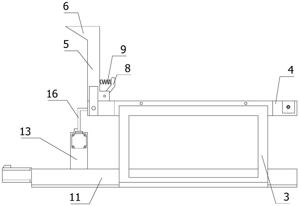
[0077] refer to Figure 1 to Figure 10 As shown, a high-precision scale synchronous blanking type thread rolling equipment includes: workbench 1;

[0078] The discharging assembly is used to place batches of metal rods 2, and the discharging assembly is arranged on the top of the workbench 1;

[0079] The push assembly is used to push the metal rod 2 on the discharge assembly, and the push assembly is arranged on the discharge assembly;

[0080] The material-moving component is used to move the metal rod 2, and the material-moving component is arranged on the top of the workbench 1, and the material-moving direction of the material-moving component is also perpendicular to the pushing direction of the pushing component;

[0081] The positioning component is used for positioning the metal rod 2, and the positioning component is arranged on the material moving component;

[0082] The grabbing component is used to grab the metal rod 2 on the discharging component to the positio...

Embodiment 2

[0126] Compared with Embodiment 1, in this embodiment, the thread rolling assembly includes:

[0127] Two rolling rollers 50 are provided, and the two rolling rollers 50 are arranged symmetrically above the workbench 1, and each rolling roller 50 is rotatably arranged on a U-shaped frame 51;

[0128] Two support plates 52 are provided, and the two support plates 52 are all fixedly arranged on the top of the workbench 1, and each support plate 52 is respectively located on the outside of each U-shaped frame 51, and the closed end of each U-shaped frame 51 has two Each side is provided with a stabilizing bar 53 through the corresponding support plate 52, and an anti-off disc 54 is also provided at the outward end of each stabilizing bar 53;

[0129] Two rotating motors 55 are provided for driving each rolling roller 50. The output end of each rotating motor 55 is connected with one end of the corresponding rolling roller 50 by a coupling. Each rotating motor 55 All are fixed on...


PUM


Abstract

The invention relates to the field of machining, in particular to high-precision scale synchronous falling type thread rolling equipment. The equipment comprises a workbench, a material placing assembly used for placing batch metal rods, a pushing assembly used for pushing the metal rods on the material placing assembly, a material moving assembly used for moving the metal rods and arranged at the top of the workbench, a positioning assembly used for positioning the metal rods, a grabbing assembly used for grabbing the metal rods on the material placing assembly to the positioning assembly, a thread rolling assembly used for conducting thread machining on the metal rods and arranged on the top of the workbench, a distance sensing assembly used for adjusting and controlling the thread machining length of the metal rods, and a discharging assembly used for directly discharging out the metal rods after thread machining. According to the high-precision scale synchronous falling type thread rolling equipment, the problems that in traditional thread rolling machining, automatic discharging cannot be achieved after machining is completed, and the thread rolling precision is not accurate are solved, the precision of metal rod thread machining is improved, and the efficiency of metal rod thread machining is improved.

Description

technical field [0001] The invention relates to the field of mechanical processing, in particular to a high-precision scale synchronous blanking type thread rolling equipment. Background technique [0002] Thread rolling strengthening is to use the elastic-plastic deformation properties of steel, use a roller that matches the shape and geometric dimensions of the fillet at the root of the thread, and apply a certain rolling force to the fillet at the root of the thread when the part rotates. A method to strengthen the thread by producing an elastic-plastic deformation layer on the metal surface. The thread rolling strengthening process is often used in the manufacturing process of aviation high-strength metal parts with MJ thread reinforced thread. It is controlled as a special process. This process combines MJ The structural characteristics of the thread significantly increase the fatigue life of the part. [0003] The screw is the main and key part of the mechanical parts...

Claims


Application Information

Patent Timeline
Patent Type & Authority Applications(China)
IPC IPC(8): B21H3/04B23G9/00B23G11/00
CPCB21H3/042B23G9/00B23G11/00
Inventor 孙航军
Owner 孙航军
Why Eureka
Try Eureka