Mechanical cutting equipment

A technology of mechanical cutting and equipment, which is applied in the direction of metal processing equipment, metal processing machinery parts, maintenance and safety accessories, etc. It can solve the problems of staying in circular grooves, poor cutting effect of iron products, and increased wear of cutting knives, etc. problem, to achieve the effect of increasing storage capacity, enhancing vibration effect, and increasing vibration effect

Active Publication Date: 2021-05-28
JINAN MINCHANG NEW ENERGY CO LTD
View PDF5 Cites 1 Cited by
  • Summary
  • Abstract
  • Description
  • Claims
  • Application Information

AI Technical Summary

Problems solved by technology

[0003] In mechanical cutting, a cutting knife is often used to cut objects, but in existing mechanical cutting equipment, if the iron product is cut for a long time, the part of the cutting knife side contacting the iron product will be circled by the iron product. When cutting iron products, the iron powder generated during the cutting process may stay in the circular groove and will not automatically break away from the cutting knife under the action of centrifugal force. After a long period of accumulation, these iron powders will be lost during the cutting process. The friction between the iron product and the cutting knife will not only cause the cutting effect of the iron product to deteriorate, but also increase the wear of the cutting knife during the cutting process, which has certain defects.

Method used


Image

  • Mechanical cutting equipment
  • Mechanical cutting equipment
  • Mechanical cutting equipment

Examples


Embodiment Construction

[0030] The following will clearly and completely describe the technical solutions in the embodiments of the present invention with reference to the accompanying drawings in the embodiments of the present invention. Obviously, the described embodiments are only some, not all, embodiments of the present invention. Based on the embodiments of the present invention, all other embodiments obtained by persons of ordinary skill in the art without making creative efforts belong to the protection scope of the present invention.

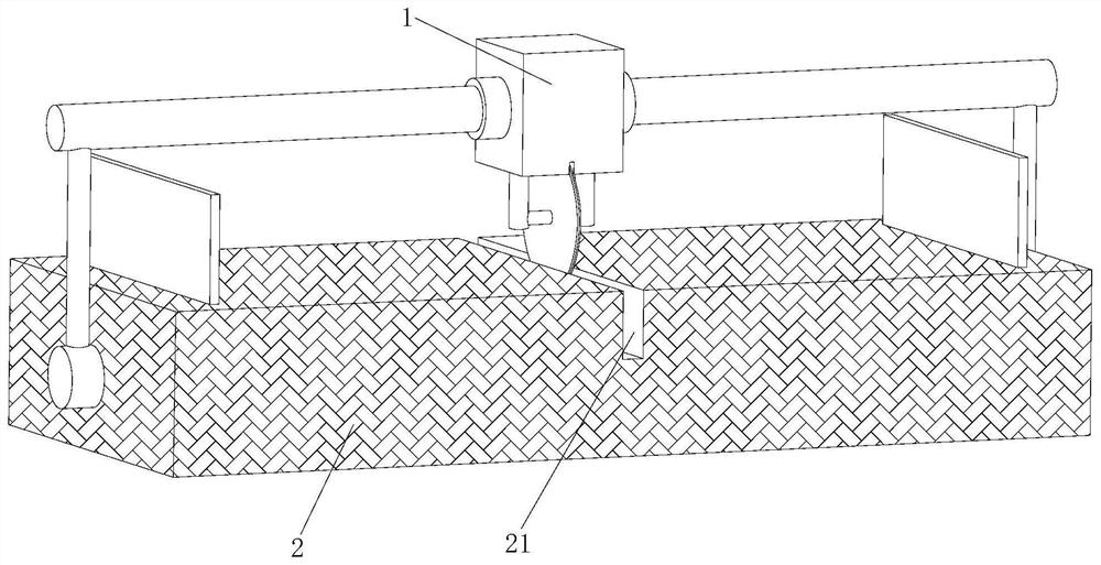
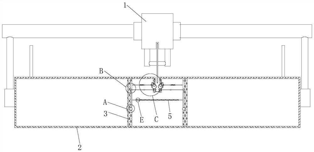
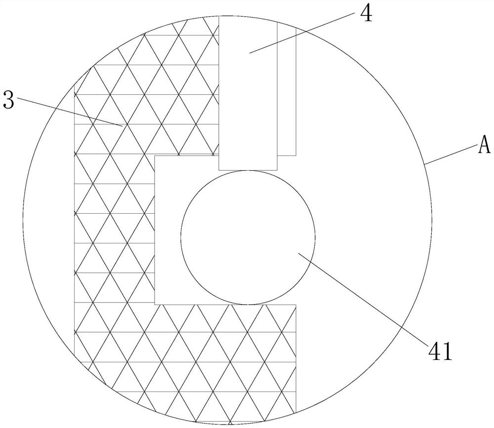
[0031] see Figure 1-9 The present invention provides a technical solution: a mechanical cutting device, including a cutting device 1 and a cutting table 2, the cutting device 1 is fixedly installed on the top of the cutting table 2, and the bottom of the cutting knife in the cutting device 1 is arranged in a cutting groove 21, The cutting groove 21 is opened on the top of the cutting table 2. Two fixing plates 3 are welded inside the cutting table 2. The adja...


PUM


Abstract

The invention discloses mechanical cutting equipment, and relates to the technical field of machining. The mechanical cutting equipment comprises a cutting device and a cutting table, wherein the cutting device is fixedly installed at the top of the cutting table, the bottom of a cutting knife in the cutting device is arranged in a cutting groove, the cutting groove is formed in the top of the cutting table in a penetrating mode, and two fixing plates are welded into the cutting table; and the close sides of the two fixing plates are slidably connected with two sliding blocks separately, a vibration plate is fixedly installed at one side of each sliding block, and an elastic ball is fixedly installed at the bottom of each sliding block. According to the mechanical cutting equipment, by arranging the hollow rubber balls, heat generated in the cutting process of the cutting knife can be utilized, the hollow rubber balls are expanded, and when the hollow rubber balls are expanded to make contact with the center of an arc-shaped hard copper sheet, a sealing block can move under the action of a pushing assembly; and gas in the hollow rubber balls is blown to the bottom of the cutting knife through an empty cavity I, so that iron powder on the cutting knife is regularly cleaned.

Description

technical field [0001] The invention relates to the technical field of mechanical processing, in particular to a mechanical cutting device. Background technique [0002] Machining refers to the process of changing the shape or performance of a workpiece through a mechanical device. According to the difference in processing method, it can be divided into cutting processing and pressure processing. Cutting is a physical action. Cutting in a narrow sense refers to cutting objects (such as food, wood and other objects with low hardness) with sharp tools such as knives; cutting in a broad sense refers to using tools, such as machine tools, flames, etc. to make objects down to disconnect. There is also a "cutting line" extended in mathematics, which refers to a straight line that can divide a plane into several parts. Cutting plays an important role in people's production and life. [0003] In mechanical cutting, a cutting knife is often used to cut objects, but in existing m...

Claims


Application Information

Patent Timeline
Patent Type & Authority Applications(China)
IPC IPC(8): B23Q11/00
CPCB23Q11/005B23Q11/0042B23Q11/02
Inventor 刘亮
Owner JINAN MINCHANG NEW ENERGY CO LTD
Why Eureka
Try Eureka