
Eureka
For R&D, Eureka makes reading and utilizing patents & technical documents easy.
Eureka AIR
Designed for self-driven R&D workflows. Generate viable solutions, solve complex R&D challenges, empower your innovation with AI.

Eureka Materials
Designed for material experts only. Revolutionize your material R&D, from search, analyze, to developing new materials.

TechResearch
Generate reliable direction feasibility study reports for your R&D in just a few steps.

TechSeek
Discover and master advanced knowledge NOW. Basics, ideas, possibilities, all at once.

TechMind
As an expert in R&D Theories, TechMind can generates customized viable solutions instantly.

TechRisk
Analyze your overall solution with one click, know your potential R&D risks in advance.

TechMonitor
Get weekly tech updates, stay abreast of the latest tech innovations and key insights.
A dust blowing device for a printing press
A technology for printing presses and vacuum cleaners, applied in printing presses, printing, general parts of printing machinery, etc., can solve the problems of easy generation of paper scraps, dust falling on paper, affecting printing quality, etc., to improve quality, paper is clean and tidy Effect
- Summary
- Abstract
- Description
- Claims
- Application Information
AI Technical Summary
Problems solved by technology
Method used
Image

Examples
Embodiment 1
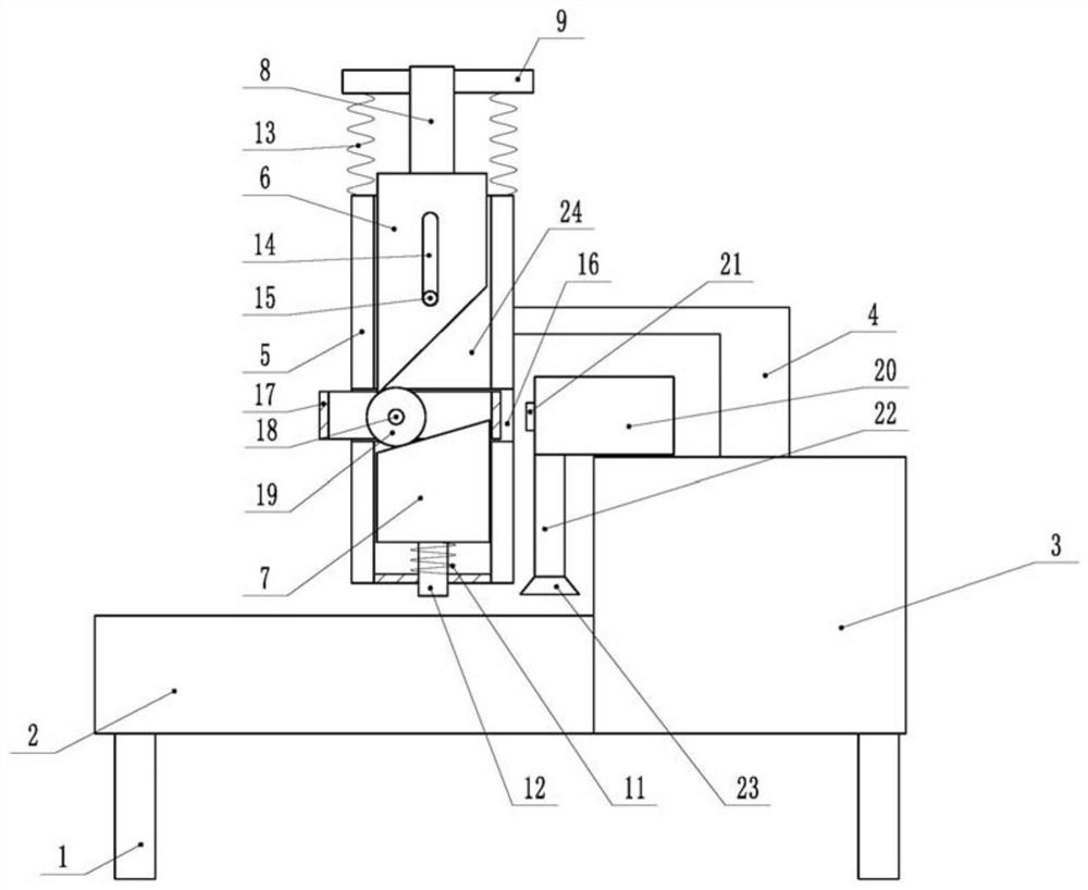
[0024] The example is basically as attached figure 1 Shown: a dust blowing device for a printing machine, comprising a transfer table 2 and a printing machine body 3, and a bracket 1 is welded and fixed to the bottom ends of the transfer table 2 and the printing machine body 3.
[0025] The printing machine body 3 is provided with a feeding port (not shown in the figure), the feeding port is located on the left side of the printing machine body 3 , and the feeding port is used for feeding paper into the printing machine body 3 for printing. The printer body 3 in this embodiment is in the prior art, and the working principle is the same as that of the printer in the prior art, which will not be repeated here.
[0026] The transfer table 2 communicates with the feeding port of the printer body 3 , and the transfer table 2 is used to transfer paper from the feeding port into the printer body 3 . A sliding plate 5 is arranged above the transfer table 2, and the sliding plate 5 is...
Embodiment 2
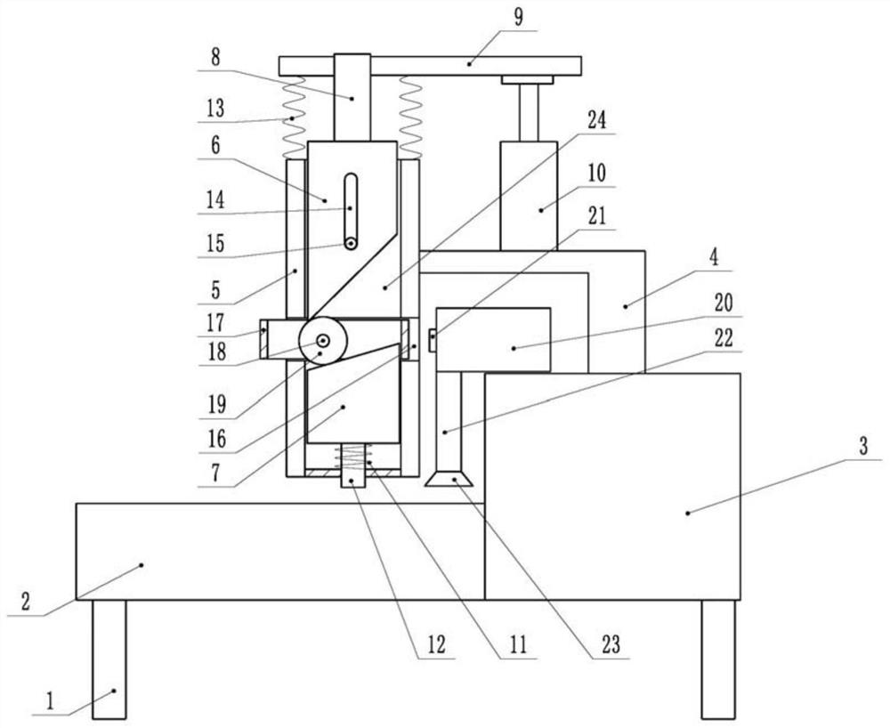
[0036] like figure 2 As shown, a dust blowing device for a printing press is different from the first embodiment in that the top end of the support frame 4 is fixedly connected with an air cylinder 10 by bolts, and the output shaft of the air cylinder 10 and the connecting plate 9 are fixedly connected by bolts.
[0037] In this embodiment, the vertical movement of the connecting plate 9 is automatically controlled by driving the air cylinder 10, thereby controlling the vertical movement of the driving plate 6. This solution does not require manual pressing of the connecting plate 9, which saves labor and labor costs.
PUM
 Abstract
Description
Claims
Application Information
 - R&D Engineer
- R&D Manager
- IP Professional
- Industry Leading Data Capabilities
- Powerful AI technology
- Patent DNA Extraction
Browse by: Latest US Patents, China's latest patents, Technical Efficacy Thesaurus, Application Domain, Technology Topic, Popular Technical Reports.
© 2024 PatSnap. All rights reserved.Legal|Privacy policy|Modern Slavery Act Transparency Statement|Sitemap|About US| Contact US: help@patsnap.com