Electromagnet tripping mechanism capable of quickly hooking and using method
A tripping mechanism and electromagnet technology, which is applied in the direction of braking components, traction connectors, brakes, etc., can solve the problems of being unable to be hooked by a single person, and achieve the effects of avoiding underground accidents and facilitating installation, use and maintenance
- Summary
- Abstract
- Description
- Claims
- Application Information
AI Technical Summary
Problems solved by technology
Method used
Image
Examples
Embodiment 1
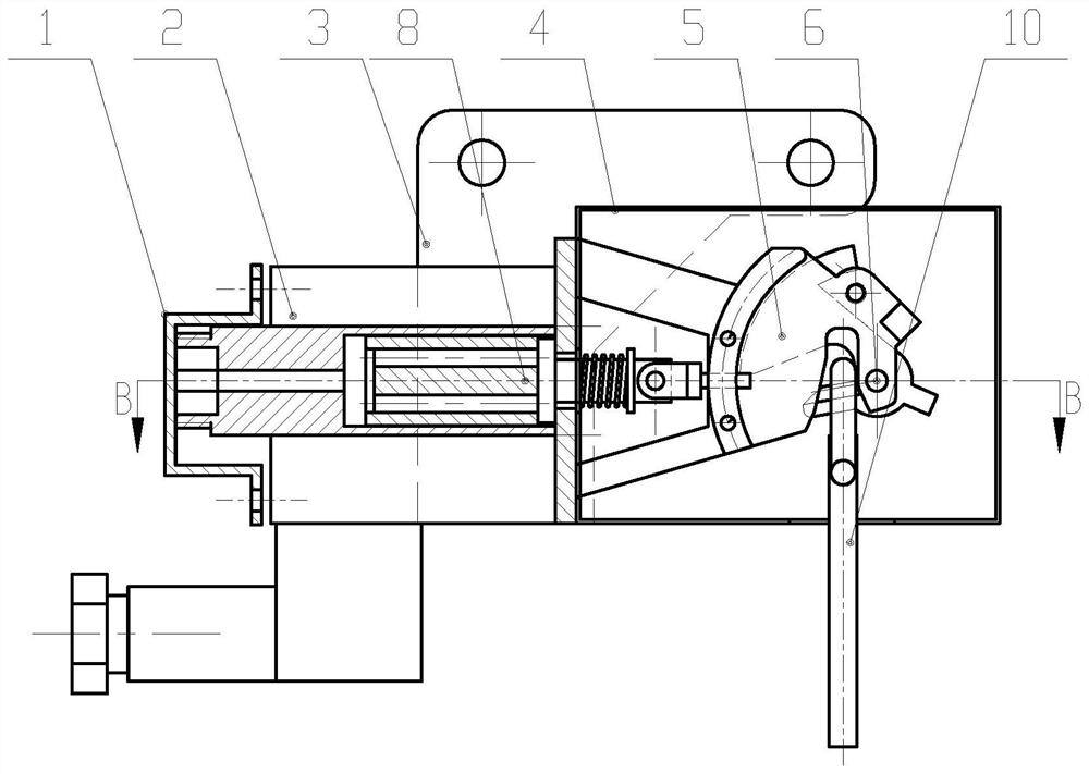
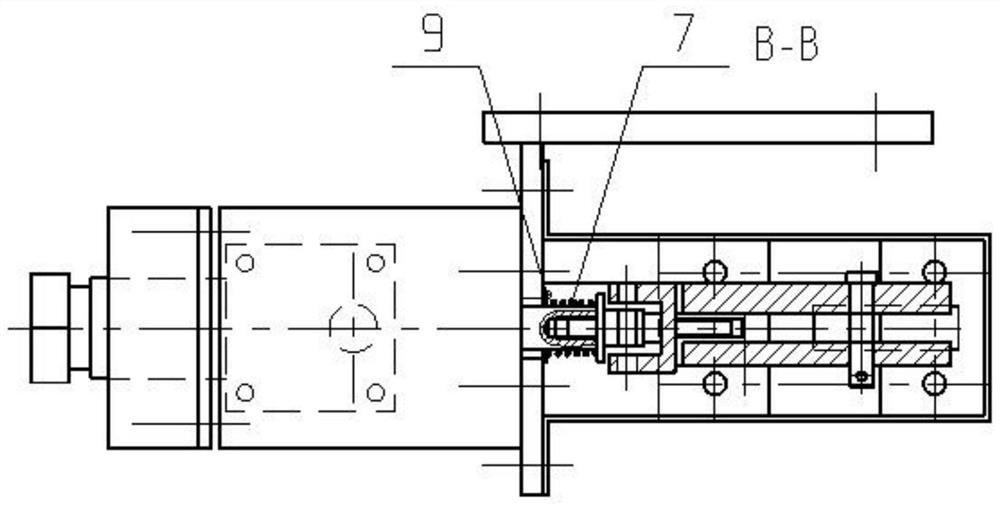
[0029] Such as figure 1 with 2 As shown, a quick-hook electromagnet release mechanism includes a gland 1, an electromagnet 2, an integral fixing frame 3, a cover 4, a swing rod 5, an iron core assembly 8, a hanging plate assembly 10, an electromagnet 2 and a cover 4 is connected to the middle part of the overall fixed frame 3 in turn from left to right, the iron core assembly 8 passes through the electromagnet 2 horizontally from left to right and the right part of the iron core assembly 8 is connected to the inside of the cover 4, the left end of the iron core assembly 8 It is connected with the left end of the electromagnet 2 through the gland 1, and the right end of the iron core assembly 8 is connected with the left part of the swing rod 5, and the right part of the swing rod 5 is movably connected with the integral fixed frame 3 in the cover 4, and the lower part of the swing rod 5 is locked. Peg plate assembly 10.
[0030] The quick hook electromagnet release mechanism...
Embodiment 2
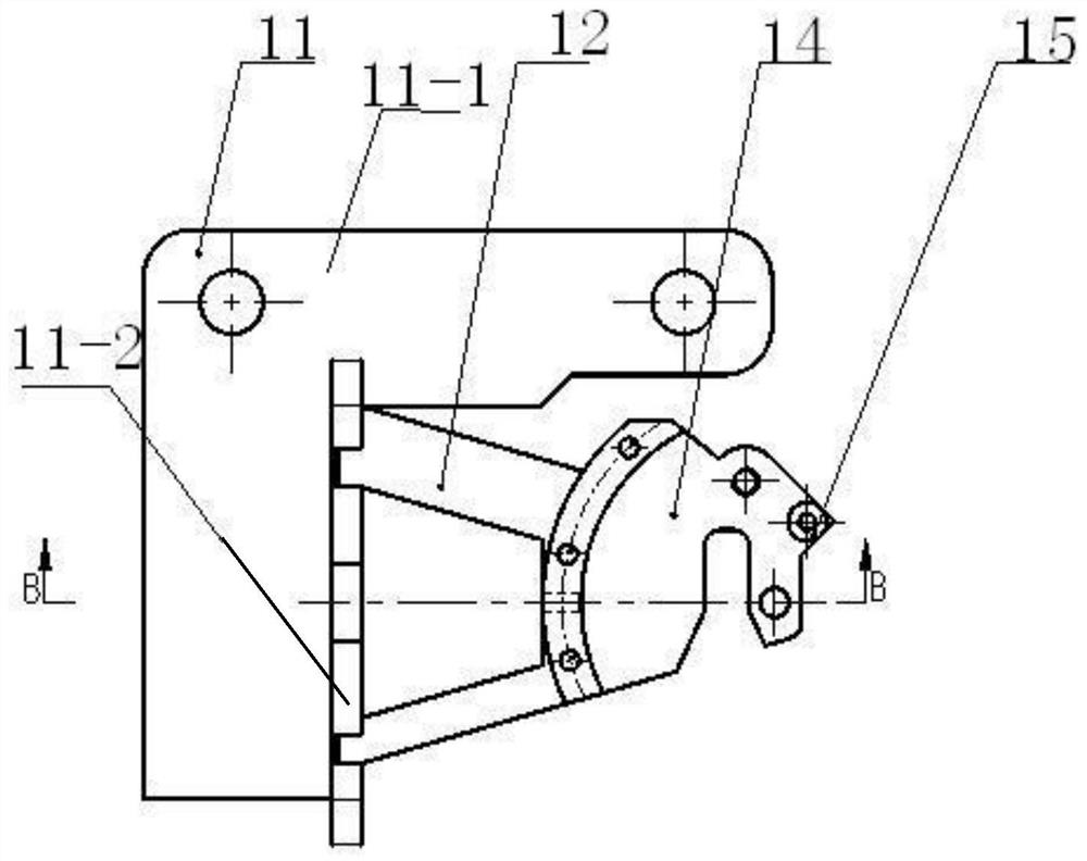
[0032] Such as image 3 with Figure 4 As shown, on the basis of Embodiment 1, the integral fixing frame 3 includes a fixing bracket 11, a base plate 12, an intermediate plywood 13 and an outer side plate 14, and the fixing bracket 11 includes a horizontal frame 11-1 and a vertical frame 11-2, The left end of the horizontal frame 11-1 is vertically connected to the vertical frame 11-2, the right end of the vertical frame 11-2 is connected to the base plate 12, and the right part of the base plate 12 is connected to the outer plate 14 through the middle splint 13, and the base plate 12 and the outer plate 14 They are all arranged vertically, and the middle splint 13 is horizontally provided with a limit hole 13-1; the electromagnet 2 passes through the vertical frame 11-2 and connects to the cover 4.
[0033] The integral fixing frame 3 fixedly connects the electromagnet 2 and the cover 4, and then stabilizes the electromagnet 2, the iron core assembly 8 and the swing rod 5 on...
Embodiment 3
[0038] Such as Figure 5As shown, on the basis of Embodiment 2, the iron core assembly 8 includes a static iron core 16, a moving iron core 17, a connecting shaft assembly 18 and a flashboard 20, and the horizontal central axis in the static iron core 16 is connected to the moving iron The core 17 and the center of the right end of the moving iron core 17 are connected to the plug board 20 through the connecting shaft assembly 18 and the connecting shaft assembly 18 and the plug board 20 are both located in the cover 4 . After the iron core assembly 8 is energized, the moving iron core 17 drives the inserting plate 20 through the connecting shaft assembly 18 to insert or protrude into the limiting hole 13-1 of the intermediate splint 13, which has a high degree of automation.
[0039] Further, the iron core assembly 8 is installed in the center hole of the coil of the electromagnet 2 to ensure that the force is balanced and the structure is stable during use.
[0040] Further...
PUM
 Abstract
Description
Claims
Application Information
 - R&D
- Intellectual Property
- Life Sciences
- Materials
- Tech Scout
- Unparalleled Data Quality
- Higher Quality Content
- 60% Fewer Hallucinations
Browse by: Latest US Patents, China's latest patents, Technical Efficacy Thesaurus, Application Domain, Technology Topic, Popular Technical Reports.
© 2025 PatSnap. All rights reserved.Legal|Privacy policy|Modern Slavery Act Transparency Statement|Sitemap|About US| Contact US: help@patsnap.com


