Eureka AIR delivers breakthrough ideas for toughest innovation challenges, trusted by R&D personnel around the world.

Power unmanned aerial vehicle inspection path planning device

A technology of inspection paths and drones, which is applied to the cooling system of power plants, motor vehicles, aircraft parts, etc., and can solve problems such as poor heat dissipation, non-adjustable, and lack of heat dissipation devices

Pending Publication Date: 2021-05-28
高源
View PDF7 Cites 0 Cited by
  • Summary
  • Abstract
  • Description
  • Claims
  • Application Information

AI Technical Summary

Problems solved by technology

[0003] Today's line inspections mostly use inspection drones. The existing power inspection drones have poor shock absorption effects, and their cameras are mostly non-fixed and cannot be adjusted. What's more, most of them lack cooling devices. The control board in the main body of the drone is only dissipated through the natural exhaust port, and the heat dissipation effect is relatively poor

Method used


Image

  • Power unmanned aerial vehicle inspection path planning device
  • Power unmanned aerial vehicle inspection path planning device
  • Power unmanned aerial vehicle inspection path planning device

Examples


Embodiment 1

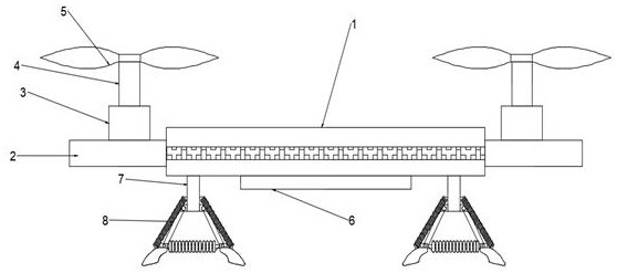
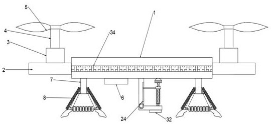
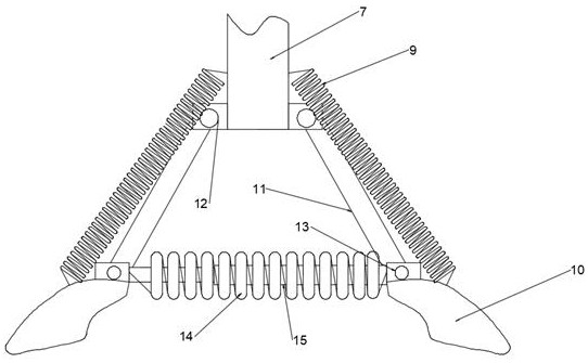
[0022] see Figure 1~5 , in an embodiment of the present invention, an electric UAV patrol inspection path planning device includes a UAV body 1, two mounting plates 2, and a cooling box 6, and the two mounting plates 2 are located on the sides of the UAV body 1. On both side walls, the mounting plate 2 is fixedly provided with a first rotating motor 3, the output end of the first rotating motor 3 is provided with a rotating shaft 4, and the top of the rotating shaft 4 is provided with a fixedly connected lifting blade 5 , the cooling box 6 is located on the bottom end wall of the UAV body 1, a control panel 16 is arranged between the inner walls of the UAV body 1, and the bottom end of the UAV body 1 communicates with the cooling box 6 Connected and the junction is fixedly provided with a heat dissipation plate 18, the top of the heat dissipation plate 18 is provided with a heat conducting sheet 17, the inner side wall of the heat dissipation box 6 is provided with a mounting...

Embodiment 2

[0026] see Figure 1~2 The difference between this example and Embodiment 1 is that the side wall of the drone body is provided with a bright light band 34, which makes it easier for the operator to observe the position of the drone, and facilitates the take-off and operation of the drone at night. Landing reduces the risk of a night flight collision.


PUM


Abstract

The invention discloses a power unmanned aerial vehicle inspection path planning device, and relates to the field of electric power inspection. The power unmanned aerial vehicle inspection path planning device comprises an unmanned aerial vehicle body and a heat dissipation box, a control panel is arranged between the inner walls of the unmanned aerial vehicle body, the unmanned aerial vehicle body communicates with the bottom end of the heat dissipation box, and a heat dissipation plate is fixedly arranged at the joint; a supporting seat is arranged at the bottom end of the unmanned aerial vehicle body, three damping mechanisms are arranged at the bottom end of the supporting seat, a telescopic rod is fixedly arranged between every two damping mechanisms, the telescopic rods are sleeved with the second springs, and the two ends of the second springs are fixedly connected with the two damping mechanisms correspondingly; the bottom end of the unmanned aerial vehicle body is further provided with a swing mechanism, and the bottom end of the swing mechanism is fixedly provided with a camera, so that the damping effect of landing of the unmanned aerial vehicle is greatly improved, the heat dissipation effect of the interior of the unmanned aerial vehicle body is improved, and the camera shooting angle of the camera is increased.

Description

technical field [0001] The invention relates to the field of electric power inspection, in particular to an electric power unmanned aerial vehicle inspection path planning device. Background technique [0002] Usually, the substation is located in a remote area, and the geographical adjustment is poor. The inspection of the equipment line has become an important task of the substation every period of time or even every day. By observing, inspecting and measuring the components of the transmission line. The purpose is to grasp the operation status of the line, find equipment defects and problems that threaten line safety in time. [0003] Today's line inspections mostly use inspection drones. The existing power inspection drones have poor shock absorption effects, and their cameras are mostly non-fixed and cannot be adjusted. What's more, most of them lack cooling devices. The control board in the main body of the drone is only dissipated through the natural exhaust port, an...

Claims


Application Information

Patent Timeline
IPC IPC(8): B64C39/02B64C25/62B64D47/08B64D33/10
CPCB64C39/02B64C25/62B64D47/08B64D33/10
Inventor 高源张宇婷辛彩芬马鹏蒋明宏刘嘉宇
Owner 高源
Why Eureka
Eureka Blog
Learn More