Plastic tank water treatment equipment

A technology for water treatment equipment and tanks, applied to underwater structures, containers, packaging, etc., can solve the problems of non-recyclable, affecting equipment life, low production efficiency, etc., to prevent outward expansion or inward shrinkage, The effect of ensuring safety strength and reducing production cost

Pending Publication Date: 2021-05-28
JIANGSU JINSHAN ENVIRONMENTAL PROTECTION TECH
View PDF0 Cites 0 Cited by
  • Summary
  • Abstract
  • Description
  • Claims
  • Application Information

AI Technical Summary

Problems solved by technology

[0002] The existing storage tanks used in the water treatment industry can be roughly divided into four categories; one is made of glass fiber reinforced plastics, usually using a winding production process, the environment in the production project is poor, and toxic gases are generated. It belongs to hazardous waste and cannot be recycled; the second is assembled and welded by steel materials, the production efficiency is low, and after the production is completed, an internal anti-corrosion layer needs to be installed. If the anti-corrosion layer is not set properly, the life of the equipment will be affected; the third is to use stainless steel materials, but the production cost is high, and a large number of applications are not used for promotion; the fourth is the plastic tank produced by the conventional rotational molding process, but the volume of the tank is small and the strength is low, which cannot meet the requirements of high strength and large volume.
[0003] At present, these four storage tanks can no longer meet the technical development requirements in the field of water treatment. Therefore, it is urgent to adopt a new type of tank body with high production efficiency, high strength, suitable for various use occasions, and green and environmentally friendly.

Method used


Image

  • Plastic tank water treatment equipment
  • Plastic tank water treatment equipment
  • Plastic tank water treatment equipment

Examples


Embodiment Construction

[0025] The present invention will be further described below in conjunction with accompanying drawing:

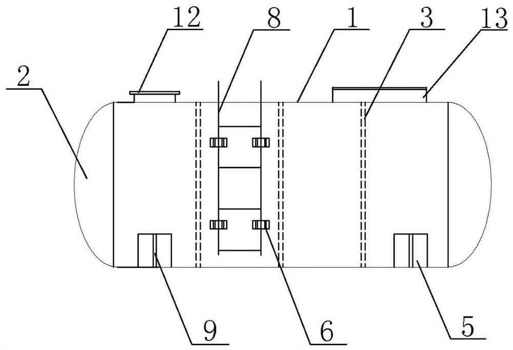
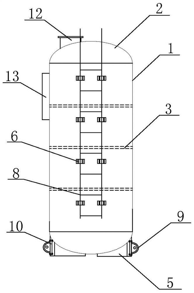
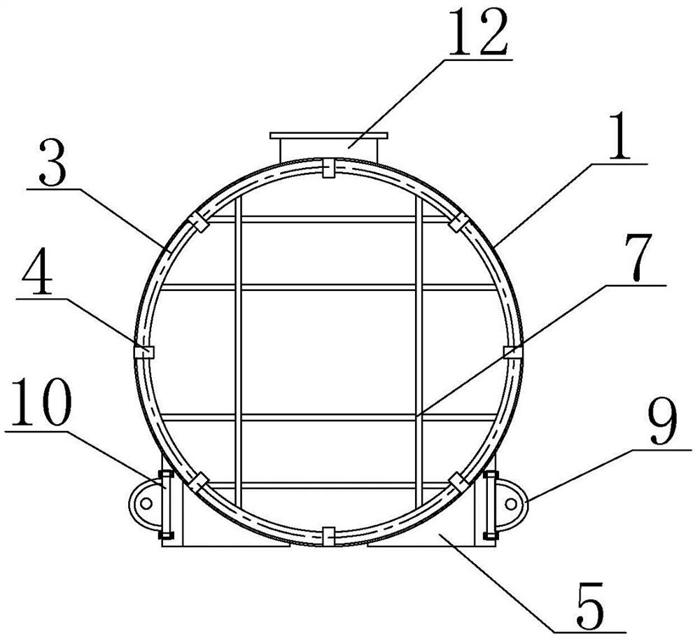
[0026] Such as Figure 1-5 As shown, the present invention includes a tank body 1. The material of the tank body 1 is PPH raw material or HDPE raw material. The PPH raw material and HDPE raw material have the characteristics of heat setting, creepability, high tension, no cracking and no toxicity. When personnel use PPH raw materials or HDPE raw materials to make the tank body 1, they can be directly wound on various types of molds for integral molding, which not only has high production efficiency but is also very environmentally friendly.

[0027] The two ends of the tank body 1 of this equipment are fixedly connected with the head 2, wherein the head 2 is fixedly connected with the two ends of the tank body 1 by fusion welding; the fusion welding process is used to fuse the connection ends of the tank body 1 and the two heads 2 Together, the tank body 1 and the head 2 a...


PUM


Abstract

The invention discloses plastic tank water treatment equipment. The equipment comprises a tank body, end sockets are fixedly connected to the two ends of the tank body, reinforcing strips are installed in the end sockets, a plurality of evenly-spaced circular rings are arranged in the tank body and tightly attached to the inner wall, and a plurality of evenly-spaced reinforcing blocks are arranged at the position, located at the periphery of the rings, of the inner wall of the tank body. Circular holes are formed in the reinforcing blocks, the head ends of the circular rings penetrate through the circular holes and then are connected with the tail end into a whole, saddle bases are arranged at the bottom of the tank body, the saddle bases are welded to the two sides of the bottom of the tank body in a two-section split charging manner, and the bottom face, located between the saddle bases, of the tank body is tightly attached to the placing face. Lifting lugs are arranged at the outer side edges of the saddle bases, reinforcing lining plates are arranged at the inner side edges of the saddle bases, the reinforcing lining plates are fixedly connected with the outer side edges of the saddle bases through bolts, the lifting lugs are welded to the reinforcing lining plates, and a ladder stand is arranged on the outer wall of the tank body. According to the equipment, the production efficiency is high, the strength is high, various use occasions are met, and the environment-friendly effect is achieved.

Description

technical field [0001] The invention belongs to the field of water treatment equipment, and in particular relates to a plastic tank water treatment equipment. Background technique [0002] The existing storage tanks used in the water treatment industry can be roughly divided into four categories; one is made of glass fiber reinforced plastics, usually using a winding production process, the environment in the production project is poor, and toxic gases are generated. It belongs to hazardous waste and cannot be recycled; the second is assembled and welded by steel materials, the production efficiency is low, and after the production is completed, an internal anti-corrosion layer needs to be installed. If the anti-corrosion layer is not set properly, the life of the equipment will be affected; the third is to use stainless steel material, but the production cost is high, and a large number of applications are not used for promotion; the fourth is the plastic tank produced by t...

Claims


Application Information

Patent Timeline
Patent Type & Authority Applications(China)
IPC IPC(8): B65D90/12B65D90/02B65D90/54B65D90/10B65D90/00
CPCB65D90/00B65D90/02B65D90/10B65D90/12B65D90/54
Inventor 钱盘生潘亚斌
Owner JIANGSU JINSHAN ENVIRONMENTAL PROTECTION TECH
Why Eureka
Try Eureka