Safety device for industrial suspension working equipment
A work equipment and safety device technology, applied in the field of industrial suspended work equipment safety devices, can solve problems such as property damage and safety problems, and achieve the effects of reducing loss, ensuring safety, and improving safety.
- Summary
- Abstract
- Description
- Claims
- Application Information
AI Technical Summary
Problems solved by technology
Method used
Image

Examples
Embodiment 1
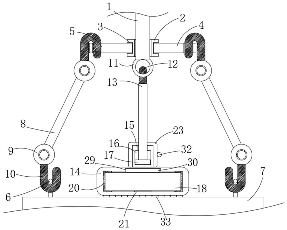
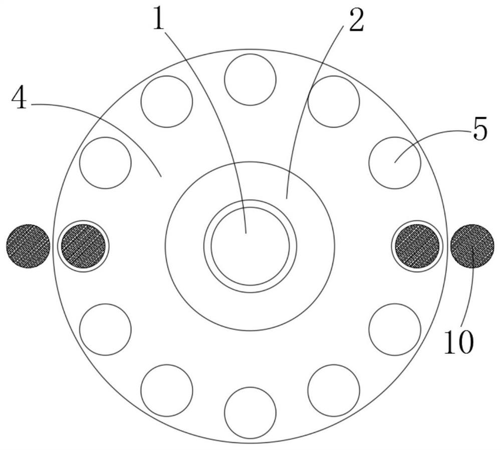
[0023] refer to Figure 1-3 , a safety device for industrial suspension work equipment, comprising a main cable 1, one end of the main cable 1 is fixedly connected with a fixed disk 2, and the side wall of the fixed disk 2 away from the main cable 1 is provided with a rotating groove 3, and the rotating groove 3 The inner rotation is connected with a rotating disc 4, and the rotating disc 4 is provided with a plurality of fixed holes 5 arranged symmetrically in the center. The setting of the plurality of fixed holes 5 facilitates the user to select an appropriate number of suspension devices in a suitable position according to the specifications of the moving material 7. The hanging and fixing work is completed on the top, wherein the two fixing holes 5 are respectively provided with a fixing ring 6 through the hanging device, and the two fixing rings 6 are jointly provided with a moving material 7. Both ends are provided with suspension rings 9, and the two suspension rings 9...
Embodiment 2
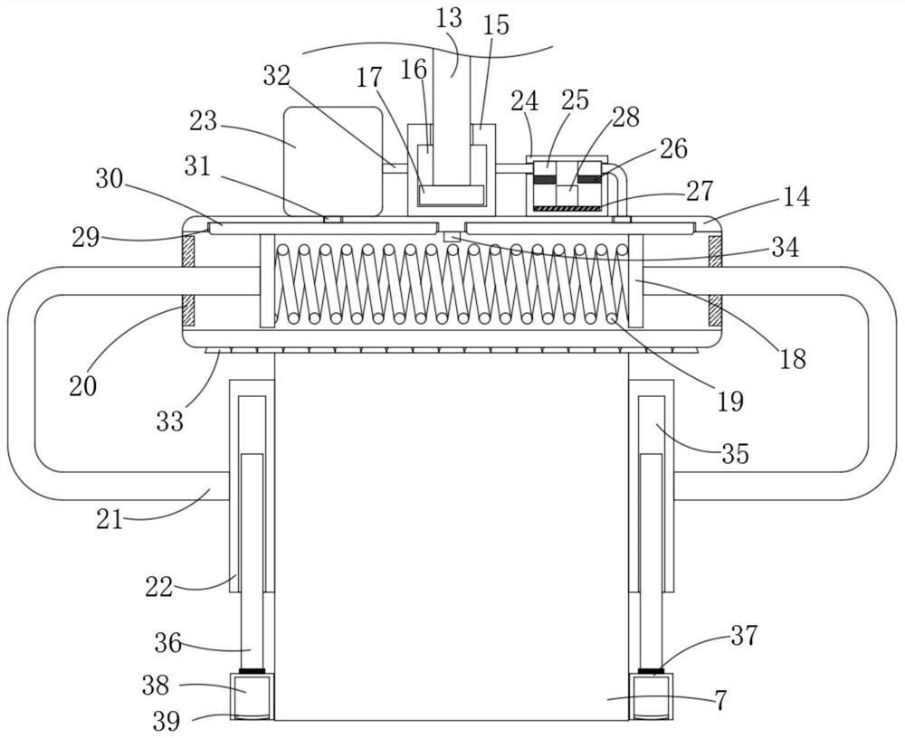
[0030] refer to figure 1 , image 3 with Figure 4 , the difference between the present embodiment and the first embodiment is the setting of two auxiliary devices, the two clamping columns 22 are equipped with auxiliary devices, the auxiliary device includes a threaded groove 35 arranged on the lower end surface of the clamping column 22, the threaded groove 35 internal threads are connected with a threaded column 36, and one end of the threaded column 36 away from the threaded groove 35 is rotatably connected with an auxiliary seat 37. The setting of the threaded groove 35 and the threaded column 36 enables the user to adjust the position of the auxiliary seat 37 by rotating the threaded column 36, and then The auxiliary seat 37 can be close to the bottom surface of the moving material 7, so that when the elastic bag 39 expands under the auxiliary seat 37, the fall protection work of the moving material 7 can be successfully completed, and the auxiliary seat 37 is far away ...
PUM
 Abstract
Description
Claims
Application Information