
Construction method for steel sheet pile support in case of boulder

A construction method and technology of steel sheet piles, which are applied to sheet pile walls, excavation, infrastructure engineering, etc., can solve the problems that steel sheet piles cannot reach the designed buried depth, hinder the construction of steel sheet piles, and cannot obtain foundation pits, etc., and achieve high practicality. The effect of application and promotion value, small soil discharge and small impact

Active Publication Date: 2021-05-28
QINGDAO TECHNOLOGICAL UNIVERSITY +7
View PDF5 Cites 0 Cited by
  • Summary
  • Abstract
  • Description
  • Claims
  • Application Information

AI Technical Summary

Problems solved by technology

There are hard natural formations at the bottom of the foundation pit when constructing the retaining wall of the foundation pit, such as boulders. If gravity cement wall support or prefabricated piles are used as foundation pit support, high-pressure rotary spraying can be used when boulders are encountered. The piles are connected to the designed pile length, or clay cofferdams are used around the foundation pit for slope support; when steel sheet piles are used for foundation pit support, boulders will hinder the construction of steel sheet piles, causing the steel sheet piles to fail to reach the design. Due to the different material properties of steel sheet piles and high-pressure jet grouting piles, it is not possible to connect piles, and the foundation pit cannot be well and safely supported. Therefore, how can we not give up using low-carbon and environmentally friendly It is a key technical problem for enterprises that the steel sheet piles can ensure the safety of foundation pit support

Method used


Image

  • Construction method for steel sheet pile support in case of boulder
  • Construction method for steel sheet pile support in case of boulder
  • Construction method for steel sheet pile support in case of boulder

Examples


Embodiment Construction

[0028] In order to understand the above-mentioned purpose, features and advantages of the present invention more clearly, the present invention will be further described below in conjunction with the accompanying drawings and embodiments. Many specific details are set forth in the following description to facilitate a full understanding of the present invention. However, the present invention can also be implemented in other ways than those described here. Therefore, the present invention is not limited to the specific embodiments disclosed below.

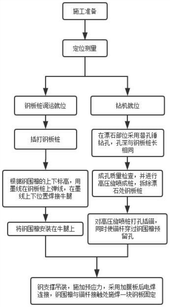
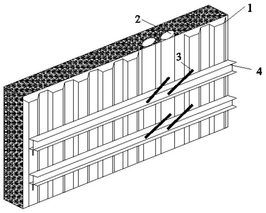
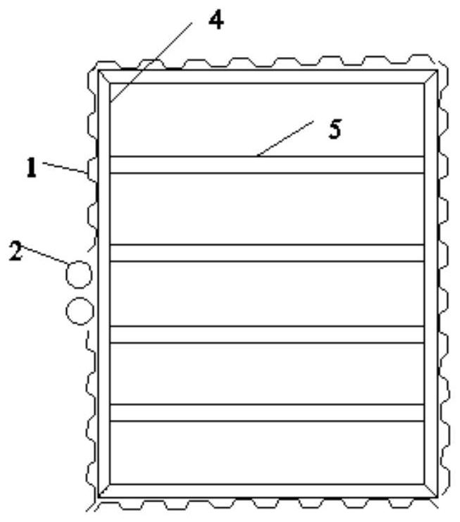
[0029] Such as Figure 2-5 As shown, the construction components involved in this embodiment include steel sheet piles 1, high-pressure rotary grouting piles 2, anchor rods 3, I-shaped steel enclosures 4, steel supports 5 and corbels 6, such as figure 1 As shown, a construction method for steel sheet pile support when encountering boulders includes the following steps:

[0030] Step 1: According to the design requirements, drive t...


PUM


Abstract

The invention belongs to the field of foundation pit excavation and support, and particularly discloses a construction method for a steel sheet pile support in the case of a boulder. A steel sheet pile is subjected to anchoring connection to form a support structure, due to the fact that the hard boulder mingled in a stratum affect construction of the steel sheet pile, a high-pressure jet grouting pile is adopted on the portion with the boulder from the ground, the other portions without the boulders are connected and supported by the steel sheet pile, two I-shaped steel enclosing purlins are erected on the middle portions of the steel sheet pile and the high-pressure jet grouting pile, the steel sheet pile and the I-shaped steel enclosing purlins are connected and fixed through welding brackets, anchor rods penetrate through the I-shaped steel enclosing purlins and are driven into the piles for fixing, and stability maintenance is conducted again by adding steel supports. The defect of improper supporting caused by a shallow burial depth of the steel sheet pile in the case of the boulder can be effectively overcome, the steel sheet pile is reserved at the other positions and the high-pressure jet grouting pile is used at the portion with the boulder, compared with row pile supporting, the soil discharging amount is small, the influence on adjacent buildings is small, in addition, all parts are welded during construction, the operation is easy, the strength is high, and the use and operation are safer.

Description

technical field [0001] The invention belongs to the field of foundation pit excavation and support, and in particular relates to a construction method when the steel sheet pile support encounters boulders. Background technique [0002] With the increasing scale of underground space development in my country, the increasing number of large-scale projects such as open-cut tunnels and subway stations have greatly promoted the development of the theory and technical level of foundation pit engineering. However, there are uncertainties in the construction of foundation pits. characteristics, complexity, variability, and concealment, and the support construction of the foundation pit must not only ensure the safety of the entire support structure during the construction process, but also control the deformation of the support structure and the deformation of the surrounding soil. The problems encountered in the excavation and support of pits are becoming more and more extensive. ...

Claims


Application Information

Patent Timeline
IPC IPC(8): E02D17/04E02D5/04E02D5/46E02D5/74
CPCE02D17/04E02D5/04E02D5/46E02D5/74
Inventor 于广明郑雯马国松李克先朱连臣樊延祥关辉刘正伟朱向飞
Owner QINGDAO TECHNOLOGICAL UNIVERSITY
Learn More