Rotary damper

A damper and connecting part technology, applied in the direction of building types, buildings, building components, etc., can solve problems such as the rotational performance of difficult nodes of energy-consuming devices

Active Publication Date: 2021-05-28
广州市建工设计院有限公司
View PDF7 Cites 4 Cited by
  • Summary
  • Abstract
  • Description
  • Claims
  • Application Information

AI Technical Summary

Problems solved by technology

Due to the rotational deformation of joints under earthquake action, traditional energy dissipation devices

Method used


Image

  • Rotary damper
  • Rotary damper
  • Rotary damper

Examples


Embodiment Construction

[0019] This part will describe the specific embodiment of the present invention in detail, and the preferred embodiment of the present invention is shown in the accompanying drawings. Each technical feature and overall technical solution of the invention, but it should not be understood as a limitation on the protection scope of the present invention.

[0020] In the description of the present invention, it should be understood that the orientation descriptions, such as up, down, front, back, left, right, etc. indicated orientations or positional relationships are based on the orientations or positional relationships shown in the drawings, and are only In order to facilitate the description of the present invention and simplify the description, it does not indicate or imply that the device or element referred to must have a specific orientation, be constructed and operated in a specific orientation, and thus should not be construed as limiting the present invention.

[0021] I...


PUM


Abstract

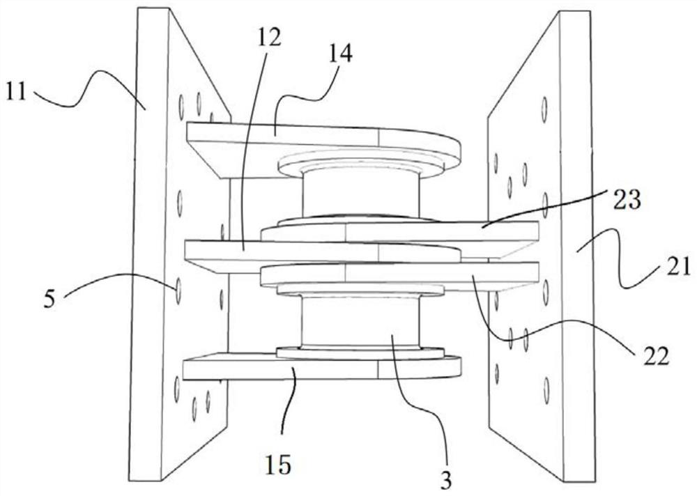
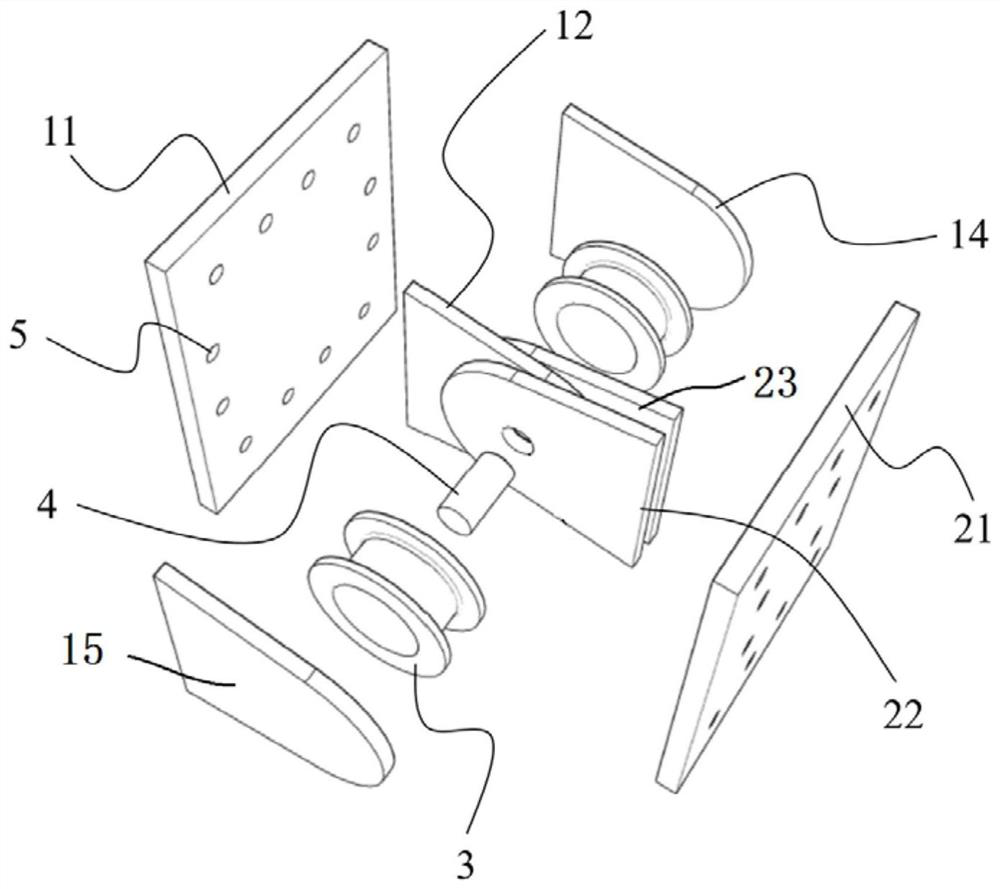
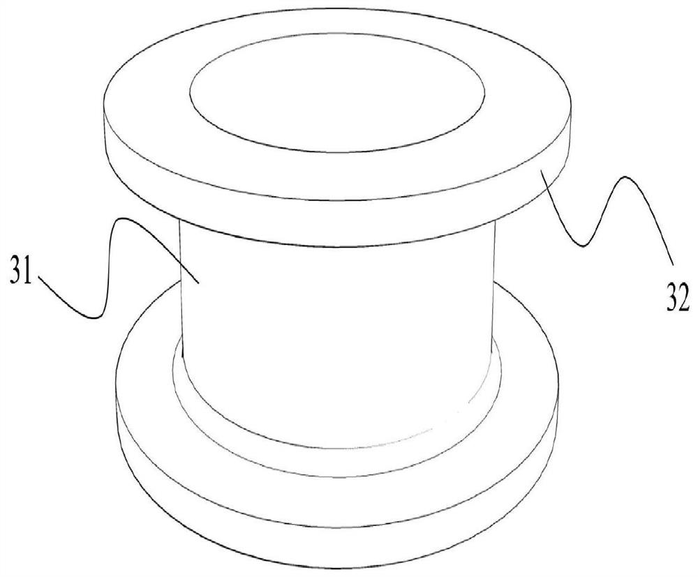
The invention discloses a rotary damper. The rotary damper comprises a mounting structure and an energy consumption structure, wherein the mounting structure comprises a first mounting part and a second mounting part which are spaced from each other; the energy consumption structure is arranged between the first mounting part and the second mounting part and comprises an energy consumption pipe assembly, a first connecting assembly and a second connecting assembly; the first connecting assembly is connected with the first mounting part and the energy consumption pipe assembly; the second connecting assembly is connected with the second mounting part and the energy consumption pipe assembly; and the first mounting part and the second mounting part move relatively to drive the energy consumption pipe assembly to be subjected to torsional deformation. The rotary damper is based on a torsional energy consumption mechanism, energy consumption can be realized by fully utilizing excellent plastic deformation performance of a metal material when the energy consumption pipe assembly is subjected to torsional deformation, the energy consumption pipe assembly is in a pure torsional stress state during working, a uniform shear stress field exists in the energy consumption pipe assembly, the situation that the bearing capacity and the fatigue performance are affected due to local buckling is not prone to occur, and the working stability and reliability are guaranteed.

Description

technical field [0001] The invention relates to the technical field of building structure energy dissipation components, in particular to a rotary damper. Background technique [0002] Under the action of earthquakes, traditional structures generate energy through the plastic deformation of the components themselves, and convert the kinetic energy input by the earthquake into the plastic strain energy of the components themselves. In order to enhance the energy-dissipating capacity of the structure and reduce the damage of components, in the existing technology, energy-dissipating devices are installed in the structure to absorb earthquake energy, and the energy-dissipating and damage are concentrated on the energy-dissipating devices themselves, thereby reducing the damage of other components. [0003] At present, the energy dissipation devices on the market can be roughly divided into the following two types according to the deformation direction: axial type and shear type...

Claims


Application Information

Patent Timeline
IPC IPC(8): E04B1/98E04H9/02
CPCE04B1/98E04H9/021
Inventor 吴从晓列文琛吴从永邓雪松
Owner 广州市建工设计院有限公司
Why Eureka
Try Eureka