Rock splitting machine capable of improving mining efficiency

A technology for splitting machines and rocks, applied in the direction of discharge machinery, earthwork drilling and mining, etc., can solve the problems of failure to prop up, waste of resources, and affect work efficiency, so as to increase hydraulic pressure, expand rock gaps, and improve The effect of the split effect

Inactive Publication Date: 2021-05-28
朱楠
View PDF0 Cites 0 Cited by
  • Summary
  • Abstract
  • Description
  • Claims
  • Application Information

AI Technical Summary

Problems solved by technology

[0003] But the existing rock splitting machine also has the following deficiencies in the actual use process. First, when the existing splitting machine is working, all the bumps are expanded outwards at the same speed synchronously under hydraulic pressure, and the rock is split. , but in the actual working process, when the rock is split, the rock crack will show a state of increasing gap width from bottom to top, similar to a V-shaped crack, which leads to the fact that when the rock crack is generated, the upper part of the splitter The bump will not be able to effectively contact the inner wall of the gap, that is, it will not be able to expand. At this time, the upper bump will do useless work, resulting in a waste of force, and the resulting hydraulic pressure is very large, which is likely to cause a waste of resources; Secondly, in the process of splitting large fragile rocks, some of the cracks may be larger when splitting. In addition, small falling rocks on both sides will accumulate on top of it, which will not only easily cause rocks to smash the splitter, but also easily get stuck in the gap, making it difficult to remove, seriously affecting work efficiency

Method used


Image

  • Rock splitting machine capable of improving mining efficiency
  • Rock splitting machine capable of improving mining efficiency
  • Rock splitting machine capable of improving mining efficiency

Examples


Embodiment Construction

[0020] The following will clearly and completely describe the technical solutions in the embodiments of the present invention with reference to the accompanying drawings in the embodiments of the present invention. Obviously, the described embodiments are only some, not all, embodiments of the present invention. Based on the embodiments of the present invention, all other embodiments obtained by persons of ordinary skill in the art without making creative efforts belong to the protection scope of the present invention.

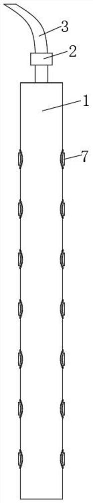
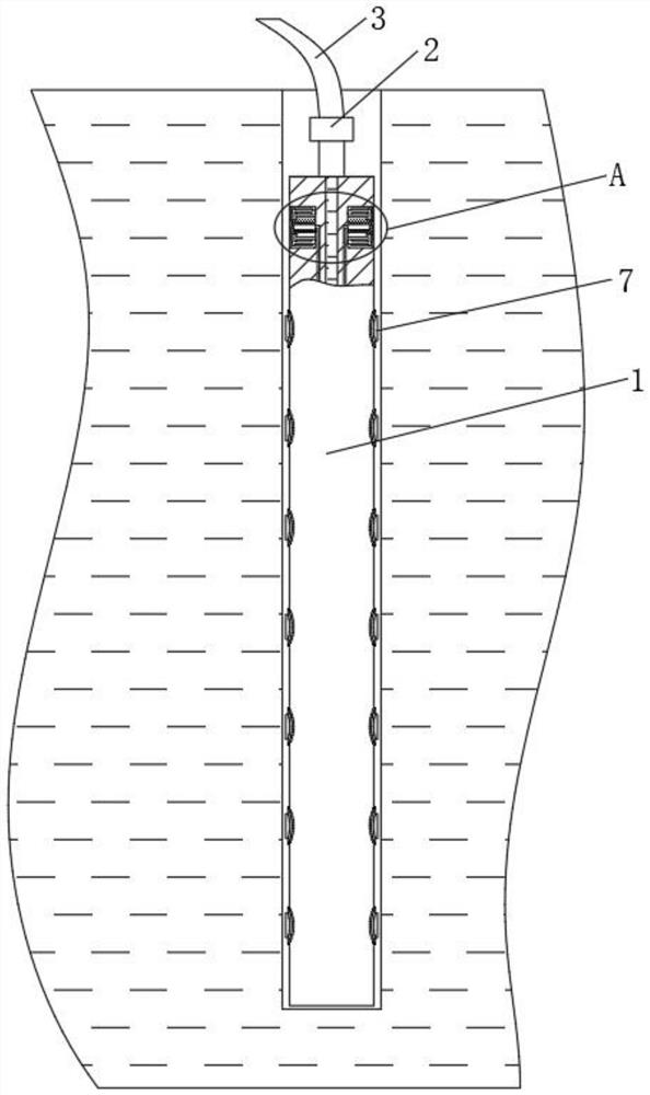
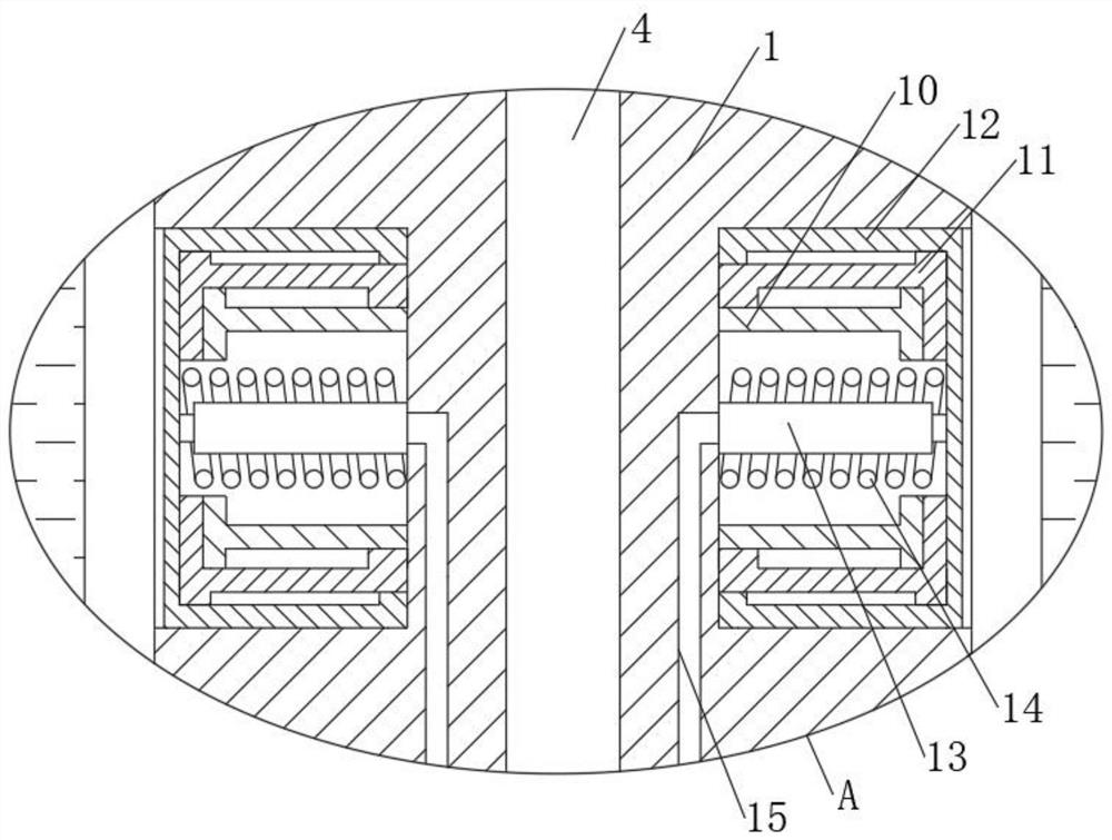
[0021] see Figure 1-6 , a rock splitting machine for improving mining efficiency, comprising a main body 1, a hydraulic connector 2 is fixedly connected to the upper end of the main body 1, a hydraulic oil pipe 3 is fixedly connected to the upper end of the hydraulic connector 2, and a hydraulic oil chamber is opened inside the main body 1 4. The upper part of the hydraulic oil chamber 4 is provided with several sets of upper limit chambers 5 inside the main ...


PUM


Abstract

The invention relates to the technical field of rock mining, and discloses a rock splitting machine capable of improving the mining efficiency. The machine comprises a main body, the upper end of the main body is fixedly connected with a hydraulic connector, the upper end of the hydraulic connector is fixedly connected with a hydraulic oil pipe, and the main body is internally provided with a hydraulic oil cavity. A plurality of upper limiting cavities formed in the main body are formed in the upper portion of the hydraulic oil cavity, and a plurality of lower limiting cavities formed in the main body are formed in the bottom of the hydraulic oil cavity. Through a telescopic rod, a return spring and each telescopic tube, when the splitting machine works, the hydraulic oil extrudes a convex block to extrude and crack rocks, the convex block is expanded, the hydraulic oil enters the telescopic rod through a communicating pipe, so that the telescopic rod overcomes the tension of the return spring under the supporting action of the hydraulic oil to drive the telescopic tubes to extend towards the two sides and abut against the two sides of a crack so as to play a fixing support role for the main body, when the rock crack is large, the splitting machine can be prevented from falling into the crack, and the splitting machine can be protected.

Description

technical field [0001] The invention relates to the technical field of rock mining, in particular to a rock splitting machine for improving mining efficiency. Background technique [0002] The splitter, also known as the splitter, is a machine used to split materials, and is mostly used in construction, decoration, engineering construction, and ore mining. The splitter consists of two parts, the hydraulic power station and the splitting gun. By placing the splitting gun in the pre-drilled hole, the ultra-high pressure oil output from the pump station drives the cylinder to generate a huge driving force, and the splitting gun mechanically After zooming in, the object to be split can be split according to the predetermined direction, so as to achieve the purpose of rock cracking. [0003] But the existing rock splitting machine also has the following deficiencies in the actual use process. First, when the existing splitting machine is working, all the bumps are expanded outwa...

Claims


Application Information

Patent Timeline
Patent Type & Authority Applications(China)
IPC IPC(8): E21C37/08
CPCE21C37/08
Inventor 不公告发明人
Owner 朱楠
Why Eureka
Try Eureka