
A method to prevent the simultaneous feeding of the boring shaft and the ram of the floor milling and boring machine

A technology for milling and boring machines and boring shafts is applied in the field of preventing simultaneous feeding of boring shafts and rams of floor milling and boring machines. Accuracy, shortening maintenance man-hours, and reducing the effect of downtime failure rate

Active Publication Date: 2022-05-31
SICHUAN COLLEGE OF ARCHITECTURAL TECH
View PDF18 Cites 0 Cited by
  • Summary
  • Abstract
  • Description
  • Claims
  • Application Information

AI Technical Summary

Problems solved by technology

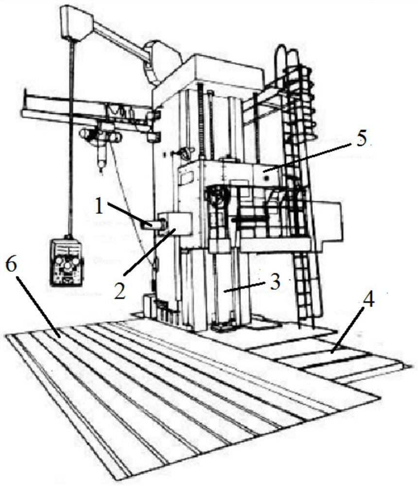
When the floor boring machine is actually working, the feeding of the boring shaft 1 and the feeding of the ram 2 share a feed box installed in the headstock 5, which can only be fed alternately and cannot be fed at the same time. The boring machine will feed the boring shaft 1 and the ram 2 at the same time. Open the headstock 5 panel and find that the reason for the simultaneous feeding phenomenon is that there is residual magnetism on the friction plate of the electromagnetic clutch after power off, and the magnetism is strong, causing friction Chip sticking and cause failure
There are two traditional maintenance methods. The first one is to remove the electromagnetic clutch and clean the friction plate, but this will take a lot of time and cannot achieve the ideal repair effect. The other maintenance method is to check the electrical external circuit and After the signals are normal, replace the electromagnetic clutch again. Although the fault can be eliminated in this way, the phenomenon of simultaneous feeding will appear after a period of time. Therefore, the traditional maintenance method will only cause the fault to recur and cannot be completely resolved.

Method used


Image

  • A method to prevent the simultaneous feeding of the boring shaft and the ram of the floor milling and boring machine
  • A method to prevent the simultaneous feeding of the boring shaft and the ram of the floor milling and boring machine

Examples


Embodiment

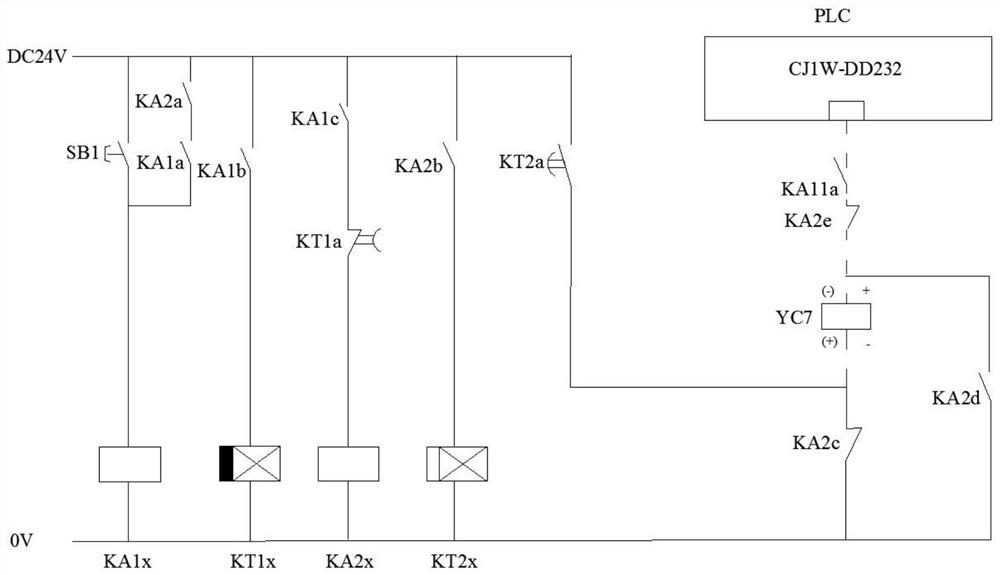
[0037] The voltage of the line to which the PLC is connected is greater than the voltage of the low-voltage power line.

[0039] The high-voltage power supply line voltage described in the present invention is 24V, and the low-voltage power supply line voltage is 0V.

[0040] In the present invention, the relay KT2 is a power-on delay relay. Relay KT2 selects delay relay energization delay

[0048] The specific time T1 is set according to the remanence of the friction plate.

[0049] The above-mentioned control circuit is used to eliminate the specific process of the remanence of the friction plate, wherein T1=300s, T2=5s:


PUM


Abstract

The invention discloses a method for preventing the simultaneous feeding of the boring shaft and the ram of a floor milling and boring machine. By adding a control circuit, the polarity direction of the power supply at both ends of the electromagnetic clutch coil YC7 in the electromagnetic clutch is changed to change the magnetic field direction of the boring shaft electromagnetic clutch Eliminate the residual magnetism produced by the friction plate in the electromagnetic clutch of the boring shaft. The method can achieve the purpose of eliminating residual magnetism on the friction plate without disassembling the electromagnetic clutch of the boring shaft of the floor milling and boring machine, and the time block for eliminating the residual magnetism has reliable performance, greatly shortens maintenance man-hours, and improves work efficiency.

Description

A method for preventing the simultaneous feeding of the boring shaft and the ram of a floor milling and boring machine technical field The invention belongs to the technical field of mechanical processing equipment, particularly a kind of preventing floor milling and boring machine boring shaft and ram from being the same time feed method. Background technique Floor milling and boring machine is a kind of heavy-duty boring machine, there is no movable table, and the workpiece is fixed on the floor platform, suitable for For machining workpieces with larger size and weight. As shown in Figure 1, a bed 4 is arranged beside the landing platform 6, and a column 3 is arranged on the bed. The column 3 is provided with a spindle box 5, the spindle box 5 moves vertically on the column 3, and the column 3 moves vertically and horizontally on the bed 4 or only to move laterally. The headstock 5 has a ram 2 that can expand and contract together with the boring shaft 1 . The ...

Claims


Application Information

Patent Timeline
Patent Type & Authority Patents(China)
IPC IPC(8): F16D27/00F16D27/14B23Q5/28
CPCF16D27/00F16D27/14B23Q5/28F16D2027/001F16D2027/002Y02P70/10
Inventor 赵强
Owner SICHUAN COLLEGE OF ARCHITECTURAL TECH
Learn More