Lamp hardware placing device

A technology for placing devices and lamps, which is applied in the field of hardware, and can solve the problems of lamps with single functions and only lighting effects

Pending Publication Date: 2021-05-28
姜海涛
View PDF0 Cites 0 Cited by
  • Summary
  • Abstract
  • Description
  • Claims
  • Application Information

AI Technical Summary

Problems solved by technology

[0005] Aiming at the deficiencies of the prior art, the present invention provides a lamp hardware placement device, which solves the problem that the existing lamps have single functions and only have lighting effects, and has an al

Method used


Image

  • Lamp hardware placing device
  • Lamp hardware placing device
  • Lamp hardware placing device

Examples


Embodiment 1

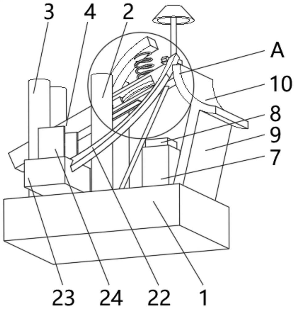
[0030] see figure 1 , the present invention provides a technical solution: a lamp hardware placement device, including a placement seat 1, the top of the placement seat 1 is symmetrically installed with a mounting frame 2 and a limit frame 3, between the two sides of the limit frame 3 An alarm board 4 is rotatably connected, the top of the placement seat 1 is fixedly connected with an elastic plate under the alarm board 4, the top of the alarm board 4 is slidingly connected with a lamp 6, and the top of the placement seat 1 is equipped with a control box 7, the control box The top of 7 is equipped with magnet piece 8, and the bottom of alarm panel 4 is equipped with the metal plate that matches with magnet piece 8, and the top of putting seat 1 is fixedly connected with condenser lens 10 by support rod 9.

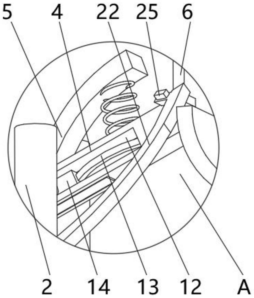
[0031] Shrink grooves 12 are provided on both sides of the alarm board 4 , and a shrink block 14 is connected to one side of the inner wall of the charging device 11 throug...

Embodiment 2

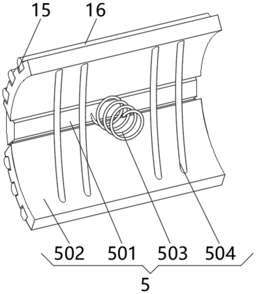
[0034] see Figure 1-3 , the present invention provides a technical solution: on the basis of Embodiment 1, a protection device 5 is installed on the top of the alarm board 4, and the protection device 5 includes a positioning block 501, and both sides of the positioning block 501 are rotatably connected with receiving plates 502, The bottom of the positioning block 501 is fixedly connected to the alarm board 4 through a protection spring 503 , and an elastic rod 504 is fixedly connected between two sides of the storage board 502 .

[0035] One side of the storage plate 502 is uniformly provided with a buffer groove 15 , and a rubber strip 16 is installed inside the buffer groove 15 , and the rubber strip 16 extends to the outside of the buffer groove 15 .

[0036]During use, the magnetized iron magnet block 8 will absorb the alarm board 4 close to the control box 7, and the receiving plate 502 will be squeezed inward to make the elastic rod 504 bend and enter between the two ...

Embodiment 3

[0038] see Figure 1-3 , the present invention provides a technical solution: on the basis of Embodiment 1, an arc-shaped sliding plate 22 is installed under the lamp 6, and the bottom of the arc-shaped sliding plate 22 is fixedly connected with a mounting block 23, and the mounting block 23 is fixed to the placement seat 1 Connection, the top of the installation block 23 is fixedly connected with the limit frame 24, and a push switch 25 is installed on one side of the lamp 6.

[0039] When in use, the alarm board 4 is attracted by the magnet block 8 and falls, the shrinkage block 14 squeezes the spring piece 13 to bend, the alarm board 4 moves one end distance to the direction of the magnet block 8, and the spring piece pushes the shrinkage block 14 to the opposite direction after the magnet block 8 is heated and demagnetized Moving, the alarm board 4 moves one end distance away from the magnet block 8 and then turns and knocks the other side of the lamp. The bottom of the la...


PUM


Abstract

The invention discloses a lamp hardware placing device which comprises a placing base, wherein a mounting frame and a limiting frame are symmetrically mounted at the top of the placing base, an alarm plate is rotatably connected between two sides of the limiting frame, an elastic plate is fixedly connected to the position, below the alarm plate, of the top of the placing base, and a protection device is mounted at the top of the alarm plate. The top of the alarm plate is slidably connected with a lamp, a control box is installed at the top of the placing base, a magnet block is installed at the top of the control box, a metal plate matched with the magnet block is installed at the bottom of the alarm plate, and the top of the placing base is fixedly connected with a collecting lens through a supporting rod. The invention relates to the technical field of hardware. According to the lamp hardware placing device, a purpose of increasing lamp functions is achieved, an alarm clock awakening function is achieved in the morning, the protection effect is good, damage caused by collision with people in a using process can be avoided, so that the power consumption in the working process is reduced, and the using cost of the device is reduced.

Description

technical field [0001] The invention relates to the field of hardware technology, in particular to a lighting hardware display device. Background technique [0002] Luminaires refer to appliances that can transmit light, distribute and change the light distribution of the light source, including all parts required to fix and protect the light source except the light source, as well as the necessary line accessories for connection to the power supply. [0003] The structure of the luminaire includes the need for hardware components, but the existing luminaire has a single function and only has lighting effects. It does not have the function of alarm clock wake-up in the early morning, and the protection effect is poor. The driving power used in the working process is more, which increases the device. The cost. Contents of the invention [0004] (1) Solved technical problems [0005] Aiming at the deficiencies of the prior art, the present invention provides a lamp hardwar...

Claims


Application Information

Patent Timeline
IPC IPC(8): F21V23/04F21V15/04F21V33/00G04B23/03
CPCF21V15/04F21V23/04F21V33/00G04B23/03
Inventor 姜海涛
Owner 姜海涛
Why Eureka
Try Eureka