Efficient pyrolysis garbage incinerator

A waste incinerator and pyrolysis technology, applied in the direction of incinerator, combustion method, combustion type, etc., can solve the problems of increasing workers, poor air circulation effect, and inability to directly interfere with the internal combustion speed, so as to improve incineration efficiency and response The effect of shortening the time

Active Publication Date: 2021-05-28
北京碧海能源装备有限公司
View PDF7 Cites 2 Cited by
  • Summary
  • Abstract
  • Description
  • Claims
  • Application Information

AI Technical Summary

Problems solved by technology

[0003] However, although traditional garbage pyrolysis equipment can incinerate garbage, because the interior of the incinerator is often under high temperature and pressure, it is easy to make the objects to be incinerated in the middle stick together. In this case, workers generally use iron tongs from the observation port. Equipment stirring, this method will increase the possibility of workers being burned, and it will also affect the incineration effect. In addition, most of the traditional incinerators are independent external bellows, and the blower takes a long time to respond from the start to the inside of the body. At the same time, it cannot directly Interfering with the internal combustion speed, some blowers have poor internal air circulation effect because the wind force is too small, and some blowers cause the combustion accelerant to be discharged without fully burning due to the wind force, making the combustion unstable

Method used


Image

  • Efficient pyrolysis garbage incinerator
  • Efficient pyrolysis garbage incinerator
  • Efficient pyrolysis garbage incinerator

Examples


Embodiment Construction

[0025] The following will clearly and completely describe the technical solutions in the embodiments of the present invention with reference to the accompanying drawings in the embodiments of the present invention. Obviously, the described embodiments are only some, not all, embodiments of the present invention. Based on the embodiments of the present invention, all other embodiments obtained by persons of ordinary skill in the art without making creative efforts belong to the protection scope of the present invention.

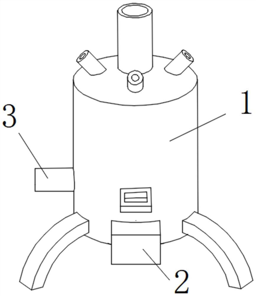
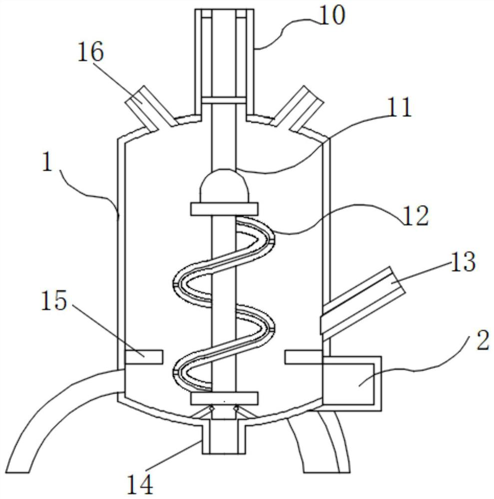
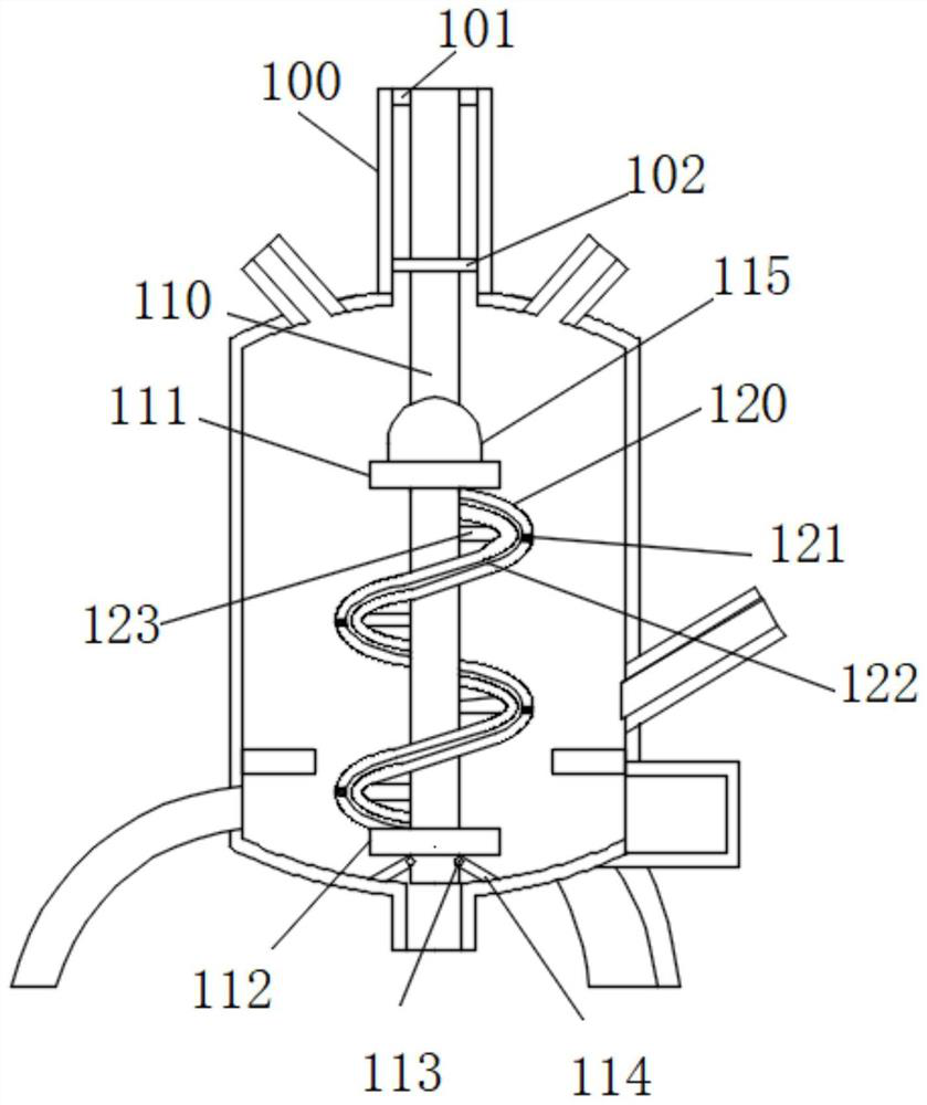
[0026] Such as Figure 1-7 As shown, the present invention provides a technical solution: a high-efficiency pyrolysis waste incinerator, including a body 1, a blower 2 is welded on the right side of the body 1, a combustion-supporting tube 3 is welded on the front of the body 1, and the body 1 includes a reciprocating mechanism 10 , the bottom of the reciprocating mechanism 10 is movably connected with a driving mechanism 11, the outer surface of the driving m...


PUM


Abstract

The invention discloses an efficient pyrolysis garbage incinerator. The efficient pyrolysis garbage incinerator comprises an incinerator body, an air blower is welded to the right side of the incinerator body, a combustion-supporting pipe is welded to the front face of the incinerator body, the incinerator body comprises a reciprocating mechanism, and the bottom of the reciprocating mechanism is movably connected with a driving mechanism. According to the efficient pyrolysis garbage incinerator, a downward-pressing rotating disc is installed inside the incinerator body, when a driving shaft rotates, the air blower blows out mixed gas of a combustion improver sprayed out of the combustion-supporting pipe and air from an air pipe through a gas guide pipe, under the reversing effect of a reversing pipe, the mixed gas is sprayed downwards, mixed gas at the bottom is sprayed upwards, the driving shaft and the rotating disc form an eccentric mechanism due to the fact that an extrusion spring pushes out a limiting pin, the volumes of air entering the air pipe in unit time are different, a rotating speed difference exists between the downward-pressing rotating disc and a driving rotating disc all the time, the mixed gas and to-be-incinerated objects are fully mixed in combination with a stirring mechanism, and therefore the incineration efficiency is improved, and the problem that incinerated objects close to the middle of a traditional incinerator are not easy to incinerate is solved.

Description

technical field [0001] The invention relates to the technical field of waste pyrolysis, in particular to a high-efficiency pyrolysis waste incinerator. Background technique [0002] Garbage pyrolysis is a relatively common method for modern urban garbage recycling. This method is to put the garbage to be incinerated into the incinerator, and apply high-temperature and high-pressure mixed gas inside the incinerator to incinerate the garbage under high-temperature incineration. This method It can recover the dust and some toxic and harmful gases produced by incineration without causing dust pollution. At the same time, it can also use the heat generated by incineration to generate electricity, which is widely used in daily life and production. [0003] However, although traditional garbage pyrolysis equipment can incinerate garbage, because the interior of the incinerator is often under high temperature and pressure, it is easy to make the objects to be incinerated in the midd...

Claims


Application Information

Patent Timeline
Patent Type & Authority Applications(China)
IPC IPC(8): F23G5/08F23G5/44F23L1/00F23L5/02
CPCF23G5/44F23G5/08F23L5/02F23L1/00
Inventor 马志卓
Owner 北京碧海能源装备有限公司
Why Eureka
Try Eureka