steam heat exchanger

A technology of heat exchanger and steam, which is applied in the direction of heat exchanger shell, steam/steam condenser, heat exchange equipment, etc. The heating device occupies a large area, etc., so as to reduce the secondary anti-corrosion operation, reduce the workload of cooling, and reduce the effect of pipe connection and installation

Active Publication Date: 2022-08-09
李永堂
View PDF9 Cites 0 Cited by
  • Summary
  • Abstract
  • Description
  • Claims
  • Application Information

AI Technical Summary

Problems solved by technology

This type of structure mainly has the following two defects: first, the heat exchange device occupies a large area, and there are many connecting pipes including headers, and the processing complexity is high. The secondary anti-corrosion process increases the difficulty of installation
Second, from the perspective of the liquid discharge effect in the middle, the effect of this type of structure is still unsatisfactory. pressure drop, because the liquid outlet header of the upper stage is a mixture of vapor and liquid phases, it is difficult to separate in the flow; in addition, because the inlet header of the next stage and the discharge header of the upper stage They are connected, and the respective outlet pipes are directly discharged. Under the action of pressure drop, part of the foam liquid will flow to the next stage inlet header.
Affect the heat transfer effect of the next stage heat exchanger

Method used


Image

  • steam heat exchanger

Examples


Embodiment Construction

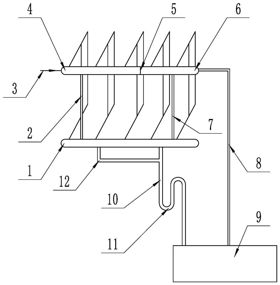
[0020] The present invention will be further described below in conjunction with the embodiments and the accompanying drawings.

[0021] like figure 1 , the embodiment of the present invention includes a composite header 1 , a first-stage steam inlet header 4 and a secondary steam inlet header 6 are arranged above the composite header 1 . The primary inlet steam header 4 is provided with an inlet steam pipe 3 . As an optimized solution, the first-stage steam inlet header 4 and the second-stage steam inlet header 6 are two sections of headers separated by the same header and separated by an internal partition 5 . The composite header 1 and the secondary inlet steam header 6 communicate with each other through a transition pipe 7 . It also includes two groups of heat exchange tubes or heat exchange plates, wherein the inlet and outlet ends of the first group of heat exchange tubes or heat exchange plates are respectively connected to the first-stage steam inlet header 4 and th...


PUM


Abstract

The invention is a steam heat exchanger, which comprises a composite header, a first-stage steam inlet header and a secondary steam inlet header are arranged above the composite header, and a transition is passed between the composite header and the secondary steam inlet header It also includes two sets of heat exchange tubes or heat exchange plates, wherein the inlet and outlet ends of the first set of heat exchange tubes or heat exchange plates are respectively connected to the first-stage steam inlet header and the composite header, and the second set of heat exchange tubes or The inlet and outlet ends of the heat exchange plate are respectively connected to the secondary steam inlet header and the composite header. The invention improves the steam flow rate along the flow direction of the condensate in the first-stage heat exchange tube and the heat exchange plate (tube) process, accelerates the discharge speed of the condensate film, greatly reduces the thickness of the condensate film, and makes it possible to generate The turbulent flow greatly improves the heat exchange efficiency in the first group of heat exchange plates (tubes). The invention greatly simplifies the pipeline structure including the header, and reduces the secondary pipeline connection between the heat exchanger groups. Make it more convenient to process and assemble.

Description

technical field [0001] The invention relates to a heat exchange device, in particular to a steam heat exchange device. Background technique [0002] There are two forms of condensation and heat transfer of steam in the tube (plate) pass. One is film condensation; the other is bead (drop) condensation. The surface heat transfer coefficient of bead condensation is several times or even an order of magnitude larger than that of film condensation. The steam is condensed in the horizontal tube (plate) pass, which is basically a film condensation. During film condensation, the wall surface is always covered by a layer of liquid film, and the phase change heat (latent heat) released during condensation must pass through the liquid film to transfer to the cooling wall surface. Therefore, the main disadvantage of film condensation is that the thermal resistance during the condensation process is mainly concentrated in the condensate film. For film condensation, in order to improv...

Claims


Application Information

Patent Timeline
Patent Type & Authority Patents(China)
IPC IPC(8): F28B1/06F28F9/00F28F9/02
CPCF28B1/06F28F9/005F28F9/02F28F2009/0285F28B9/08F28D1/03F28D1/047F28F9/0209F28F2250/06F28B1/02
Inventor 李永堂
Owner 李永堂
Why Eureka
Try Eureka