Vapor-liquid separation device

A technology of vapor-liquid separation and vapor-liquid mixing, which is applied in liquid cleaning methods, heating water/sewage treatment, water/sewage treatment, etc., and can solve the problems of heavy salt liquid entrainment in secondary steam and poor vapor-liquid separation performance , to achieve the effect of improved secondary steam separation ability, strong vapor-liquid separation ability, and improved vapor-liquid separation ability

Pending Publication Date: 2021-09-17
BEIJING JINDAYU ENVIRONMENT TECH CO LTD
View PDF0 Cites 0 Cited by
  • Summary
  • Abstract
  • Description
  • Claims
  • Application Information

AI Technical Summary

Problems solved by technology

Evaporation crystallization generally adopts multi-effect evaporation or MVR evaporation crystallization process. The high-concentration salt solution heated by this process realizes the separation of secondary steam and salt solution in the vapor-liquid separation device. However, most of the existing vapor-liquid separation devices have vapor-liquid Poor separation performance, heavy salt entrained by secondary steam, etc.

Method used


Image

  • Vapor-liquid separation device

Examples


Embodiment 1

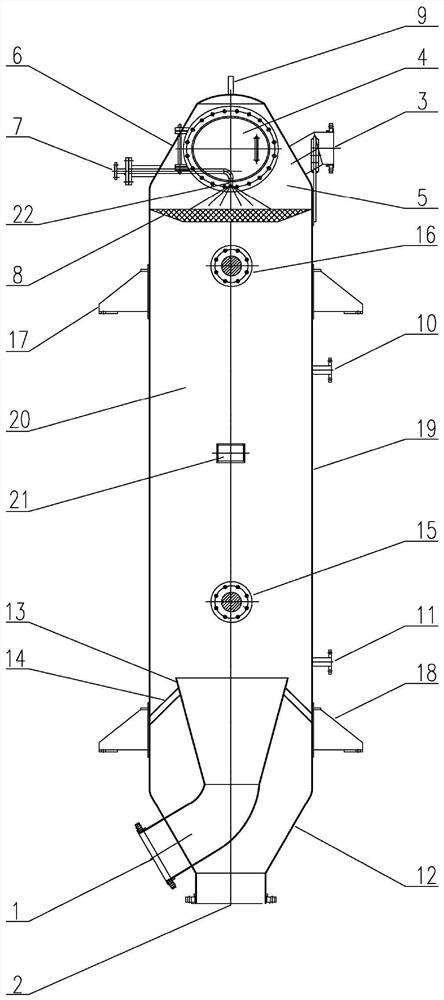
[0027] Such as figure 1 As shown, the vapor-liquid separation device of the present embodiment comprises a vapor-liquid mixing chamber 20, a steam chamber 5, a liquid-dispersing cylinder 13 and a demister 8, the liquid-dispersing cylinder 13 is arranged at the bottom of the vapor-liquid mixing chamber 20, and the liquid-dispersing cylinder 13 The inlet end of the liquid tank 13 communicates with the material water inlet 1, and the outlet end of the bulk liquid cylinder 13 communicates with the vapor-liquid mixing chamber 20. The steam chamber 5 is arranged above the vapor-liquid mixing chamber 20 and communicates with the vapor-liquid mixing chamber 20 through the demister 8. A material water outlet 2 is provided at the lower end of the vapor-liquid mixing chamber 20, and a secondary steam outlet 3 is provided at the upper end of the steam chamber 5.

[0028] In this embodiment, the vapor-liquid mixing chamber 20 is mainly used for the separation of water and steam in the mate...

Embodiment 2

[0037]This embodiment uses the vapor-liquid separation device of Embodiment 1 to separate the material water formed by the secondary steam in the multi-effect evaporation crystallization process; wherein, the height-to-diameter ratio of the cylinder 19 is set to 3.2, and the outlet end of the bulk liquid cylinder 13 is connected to the The vertical height between the lower liquid level gauge interfaces 11 is set to 300 mm, and the vertical height between the cleaning nozzle 22 and the demister 8 is set to 300 mm.

[0038] The quality index of material water is: pH=6-8, COD=150mg / L, ammonia nitrogen=25mg / L, total hardness (as CaCO 3 )=10mg / L, total alkalinity (as CaCO 3 )=300mg / L, chloride ion=27500mg / L, conductivity=113500μs / cm.

[0039] The separation process steps are as follows: the internal surface area of ​​the vapor-liquid separation device in embodiment 1 is 25m 2 , will be 30m 3 The above-mentioned material water is input into the steam heater through the circulatin...


PUM

PropertyMeasurementUnit
Total alkalinityaaaaaaaaaa
Conductivityaaaaaaaaaa
Average conductivityaaaaaaaaaa

Abstract

The invention provides a vapor-liquid separation device. The vapor-liquid separation device comprises a vapor-liquid mixing chamber, a vapor chamber, a liquid dispersing cylinder and a demister, the liquid dispersing cylinder is arranged on the lower portion of the vapor-liquid mixing chamber, the inlet end of the liquid dispersing cylinder communicates with a material water inlet, the outlet end of the liquid dispersing cylinder communicates with the vapor-liquid mixing chamber, and the vapor chamber is arranged above the vapor-liquid mixing chamber and communicates with the vapor-liquid mixing chamber through the demister. A material water outlet is formed in the lower end of the vapor-liquid mixing chamber, and a secondary vapor outlet is formed in the upper end of the vapor chamber. The vapor-liquid separation device disclosed by the invention can be suitable for separation of secondary vapor in a multi-effect evaporative crystallization process and an MVR evaporative crystallization process, and has the characteristics of high vapor-liquid separation capacity, small occupied area, low equipment investment and the like, and the secondary vapor separated by the vapor-liquid separation device does not have undesirable phenomena that salt liquid is carried in the secondary vapor and the like.

Description

technical field [0001] The invention relates to the technical field of wastewater treatment, in particular to a vapor-liquid separation device. Background technique [0002] Wastewater discharged in the production process of petrochemical, coal chemical, metallurgy, pharmaceutical, printing and dyeing, papermaking and other industries has the characteristics of high salt and high organic matter, usually with a salt content of more than 3000mg / L and a COD of more than 2000mg / L. At the same time, it contains a large amount of toxic and harmful organic compounds such as aromatic compounds, heterocyclic compounds, and hydrocarbon compounds. Even if it is discharged into the water body after treatment, it will still cause safety hazards to the water environment. Therefore, many local governments require such enterprises to achieve zero liquid discharge, referred to as zero discharge. [0003] At present, the zero-discharge treatment process for high-salt and high-organic waste w...

Claims


Application Information

Patent Timeline
IPC IPC(8): C02F1/10C02F1/04B08B3/02
CPCC02F1/10C02F1/041C02F1/048B08B3/02
Inventor 张琪曹真张继超吴冠龙王妙婷曹普晅张万松耿天甲乔文文
Owner BEIJING JINDAYU ENVIRONMENT TECH CO LTD
Why Eureka
Try Eureka