
Portable intelligent current clamp device convenient to support

A current clamp and intelligent technology, applied in the field of current clamps, can solve the problems of inability to quickly and effectively complete current detection, inability to effectively ensure personnel safety, unstable clamping of current clamps, etc., to reduce personnel climbing and high reliability , The effect of clamping the wire stably

Pending Publication Date: 2021-05-28
SHANGHAI MUNICIPAL ELECTRIC POWER CO
View PDF4 Cites 0 Cited by
  • Summary
  • Abstract
  • Description
  • Claims
  • Application Information

AI Technical Summary

Problems solved by technology

[0003] However, current clamps currently on the market require personnel to climb to the wire accessories for clamping detection when detecting wires at a higher position, which cannot effectively ensure the safety of personnel during detection, and at the same time, it is sometimes difficult for personnel to touch during detection. As a result, the current clamp is easy to affect the detection data due to the unstable clamping during detection, so that the current detection cannot be completed quickly and effectively.

Method used


Image

  • Portable intelligent current clamp device convenient to support
  • Portable intelligent current clamp device convenient to support
  • Portable intelligent current clamp device convenient to support

Examples


Embodiment Construction

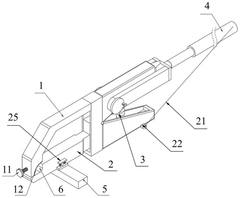
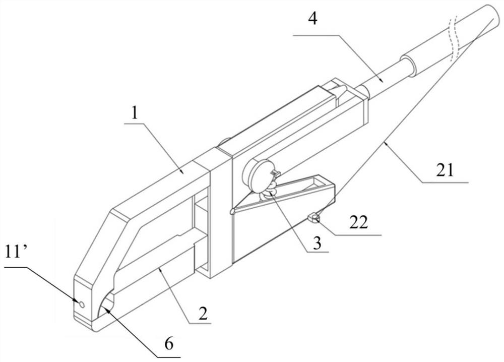
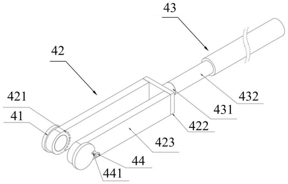
[0034] A portable intelligent current clamp device that is easy to support proposed by the present invention will be further described in detail below with reference to the accompanying drawings and specific embodiments. The advantages and features of the present invention will become clearer from the following description. It should be noted that the drawings are in a very simplified form and all use imprecise scales, which are only used to facilitate and clearly assist the purpose of illustrating the embodiments of the present invention. In order to make the objects, features and advantages of the present invention more comprehensible, please refer to the accompanying drawings. It should be noted that the structures, proportions, sizes, etc. shown in the drawings attached to this specification are only used to match the content disclosed in the specification, for those who are familiar with this technology to understand and read, and are not used to limit the implementation ...


PUM


Abstract

The invention relates to the technical field of current clamps, in particular to a portable intelligent current clamp device convenient to support. The portable intelligent current clamp device comprises an upper clamp, a lower clamp, a reset spring and a lengthening rod assembly, wherein the middle of the upper clamp and the middle of the lower clamp are fixed in a hinged mode, the front end of the upper clamp and the front end of the lower clamp are connected in an engaged mode to form a clamping opening, the rear ends of the upper clamp and the lower clamp are connected through the reset spring, the rear ends of the upper clamp and the lower clamp are squeezed to enable the rear ends of the upper clamp and the lower clamp to be close to each other so as to open the clamping opening, the clamping opening can be meshed through elastic force of the reset spring after squeezing is removed, one end of the lengthening rod assembly is rotationally connected with the rear end of the upper clamp through a rotating shaft, the other end of the lengthening rod assembly is used for handheld operation, the rear end of the lower clamp is fixedly connected with a linkage rope, and the linkage rope is pulled to control the lower clamp to rotate. The portable intelligent current clamp device is suitable for high-position wire detection, is convenient to place, is safer to operate, is suitable for wires with different diameters, and is high in wire clamping stability.

Description

technical field [0001] The invention relates to the technical field of current clamps, in particular to a portable intelligent current clamp device that is easy to support. Background technique [0002] The current clamp refers to the clamping clamp used to detect the current. It is generally used in conjunction with the ammeter. When in use, the wire is placed at the position of the jaw, the wire is clamped, and the ammeter is connected to the current clamp through a wire. Thus, current detection is performed. [0003] However, current clamps currently on the market require personnel to climb to the wire accessories for clamping detection when detecting wires at a higher position, which cannot effectively ensure the safety of personnel during detection, and at the same time, it is sometimes difficult for personnel to touch during detection. As a result, the current clamp is likely to affect the detection data due to the unstable clamping during the detection, so that the c...

Claims


Application Information

Patent Timeline
IPC IPC(8): G01R1/04
CPCG01R1/0425
Inventor 杨鹏举王涛云孟垂攀杨恒陈佳盈周明辉姚正平张颢蒋晨耀
Owner SHANGHAI MUNICIPAL ELECTRIC POWER CO
Learn More