
Shock absorption and heat dissipation electric power cabinet for electric power engineering

A technology for power engineering and power cabinets, applied in the field of shock absorption and heat dissipation power cabinets, can solve the problems of inconvenient movement and fixation, poor shock resistance of power cabinets, and unfavorable internal power equipment to work normally, and achieve the effect of ensuring normal work.

Pending Publication Date: 2021-05-28
杨楠
View PDF0 Cites 0 Cited by
  • Summary
  • Abstract
  • Description
  • Claims
  • Application Information

AI Technical Summary

Problems solved by technology

[0002] The power cabinets in the prior art have poor shock resistance and are not easy to move and fix. In earthquake-prone areas, large vibrations will cause damage to the power cabinets and lead to dangerous situations. In addition, in order to protect the instruments loaded inside, the traditional power cabinets There are usually cooling holes, and the heat dissipation performance of the simple cooling hole structure is poor, which is not conducive to the normal operation of internal electrical equipment

Method used


Image

  • Shock absorption and heat dissipation electric power cabinet for electric power engineering
  • Shock absorption and heat dissipation electric power cabinet for electric power engineering
  • Shock absorption and heat dissipation electric power cabinet for electric power engineering

Examples


Embodiment Construction

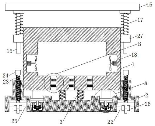
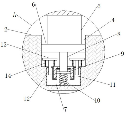
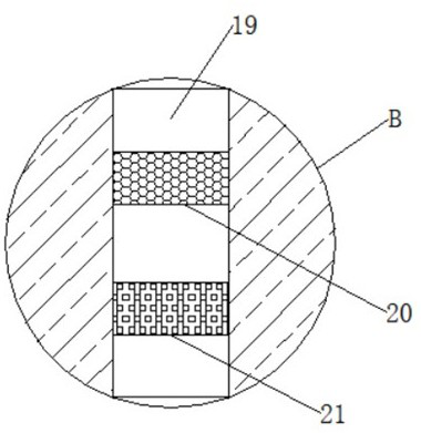
[0017] Attached below Figure 1-3 The specific implementation manner of the present invention will be described in further detail.

[0018] Depend on Figure 1-3 Given, the present invention provides the following technical solutions: a shock-absorbing and heat-dissipating power cabinet for power engineering, comprising a cabinet 1 and a shock-absorbing base 2, the cabinet 1 is arranged above the shock-absorbing base 2, the cabinet 1 and the shock-absorbing base 2 The first shock absorbing spring 3 is arranged between the shock bases 2, the upper surface of the shock absorbing base 2 is respectively provided with shock absorbing grooves 4 on both sides, and the lower side of the cabinet body 1 is fixedly connected with a pole extending to the inside of the shock absorbing groove 4. 5. The bottom of the support rod 5 is fixedly connected with a slide plate 6, and the inner sides of the shock-absorbing base 2 are respectively provided with a sealed cavity 7, and the bottom of t...


PUM


Abstract

The invention discloses a shock absorption and heat dissipation electric power cabinet for electric power engineering. The shock absorption and heat dissipation electric power cabinet comprises a cabinet body and a shock absorption base; the cabinet body is arranged above the shock absorption base; a first damping spring is arranged between the cabinet body and the shock absorption base; and shock absorption grooves are respectively formed in two sides of the upper surface of the shock absorption base; the lower side of the cabinet body is fixedly connected with supporting rods extending into the shock absorption grooves; the bottoms of the supporting rods are fixedly connected with sliding plates; sealing cavities are formed in the two sides of the interior of the shock absorption base respectively; the bottoms of the sliding plates are fixedly connected with movable rods extending into the sealing cavities; the bottoms of the movable rods are fixedly connected with large pistons; the bottoms of the large pistons are fixedly connected with reset springs; and small pistons are arranged on the two sides of the interior of each sealing cavity correspondingly. The shock absorption and heat dissipation electric power cabinet for the electric power engineering is novel in structure and ingenious in conception, has good heat-dissipating and shock-absorbing effects, can guarantee normal work of electric power equipment in the electric power cabinet, and is relatively high in practicability.

Description

technical field [0001] The invention relates to the technical field of power equipment, in particular to a shock-absorbing and heat-dissipating power cabinet for power engineering. Background technique [0002] The power cabinets in the prior art have poor shock resistance and are not easy to move and fix. In earthquake-prone areas, large vibrations will cause damage to the power cabinets and lead to dangerous situations. In addition, in order to protect the instruments loaded inside, the traditional power cabinets Usually, there are heat dissipation holes, and the heat dissipation performance of the simple heat dissipation hole structure is poor, which is not conducive to the normal operation of the internal electrical equipment. Contents of the invention [0003] In view of the above situation, in order to overcome the defects of the prior art, the present invention provides a shock-absorbing and heat-dissipating power cabinet for electric power engineering. And shock a...

Claims


Application Information

Patent Timeline
IPC IPC(8): H02B1/56H02B1/54H02B1/52H02B1/50H02B1/28H02B1/30H02B1/32
CPCH02B1/28H02B1/303H02B1/306H02B1/32H02B1/50H02B1/52H02B1/54H02B1/565
Inventor 杨涛杨楠
Owner 杨楠
Learn More