Energy-saving motor with efficient heat dissipation

A heat dissipation mechanism and high-efficiency technology, applied in the direction of electromechanical devices, electrical components, electric components, etc., can solve the problems of lack of contact heat dissipation ability, lack of continuous heat dissipation ability, and affecting air circulation, etc., to improve efficient heat dissipation ability and ensure disassembly and assembly portability The effect of ensuring the stability of the assembly

Pending Publication Date: 2021-05-28
SHENZHEN YIJI MFG CO LTD
View PDF1 Cites 6 Cited by
  • Summary
  • Abstract
  • Description
  • Claims
  • Application Information

AI Technical Summary

Problems solved by technology

[0004] The purpose of the present invention is: in order to solve the problem of dissipating heat only through the air flow driven by the air passage, there is a lack of certain contact heat dissipation ability, and at the same time, the dust in the air is easy to stay in the air passage to affect the air circulation, and when the heat continues to be generated, there is no continuous heat dissipation. Heat dissipation capacity, and the problem of inconvenient disassembly and maintenance, and a high-efficiency heat dissipation energy-saving motor is proposed

Method used


Image

  • Energy-saving motor with efficient heat dissipation
  • Energy-saving motor with efficient heat dissipation
  • Energy-saving motor with efficient heat dissipation

Examples


Embodiment approach

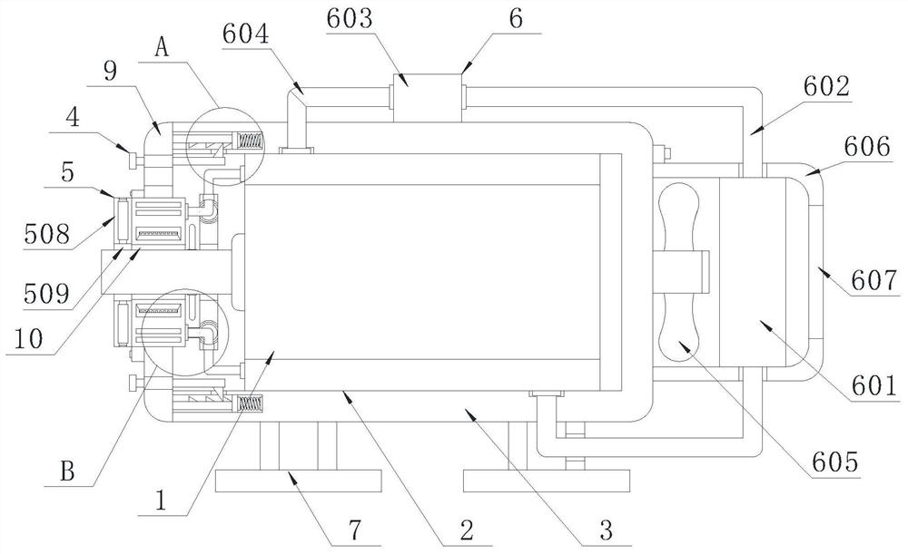
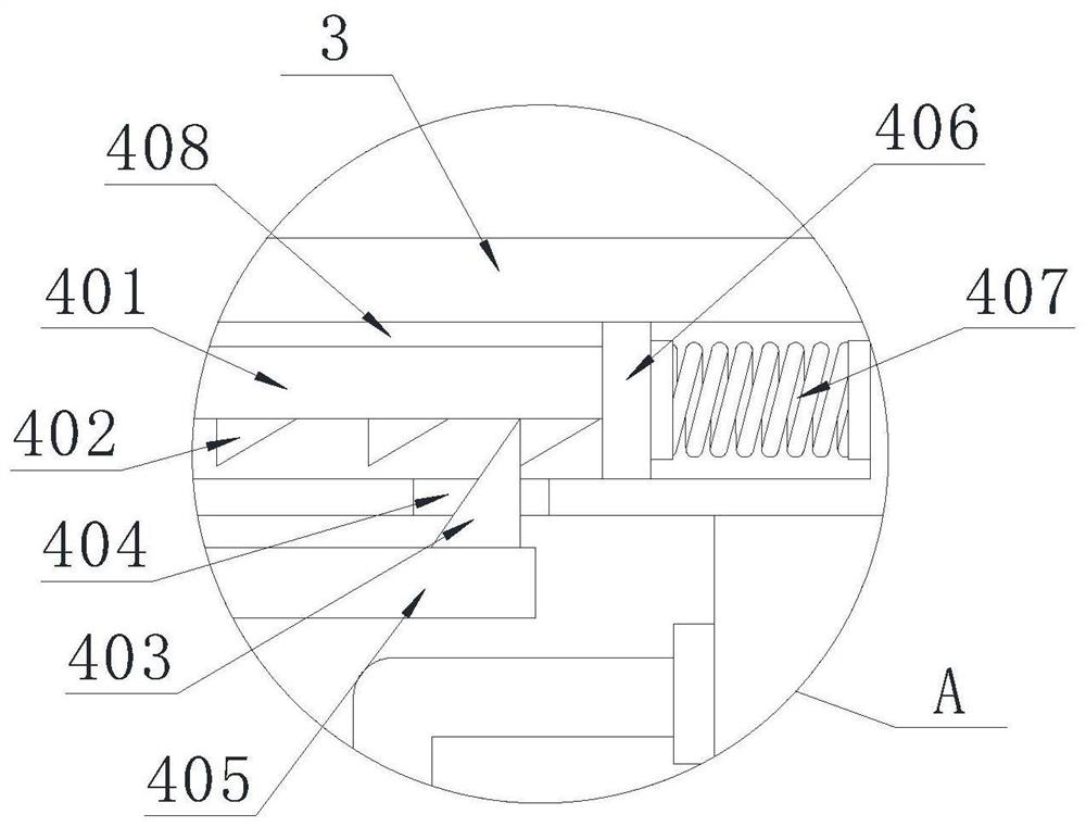
[0041] The implementation is as follows: when the motor assembly 1 needs to be maintained, the rotating rod 405 is driven to rotate by turning the rear handle, and the rotating rod 405 can drive the side stopper 403 to separate from the teeth 402. At this time, the spring 407 can be used Self-elastic force drives one side slide plate 406 to slide in the chute 408, and the movement of the slide plate 406 can extrude one side stop bar 401 to move to the outside. Quickly separate the cover plate 9 from the protective case to facilitate cleaning and maintenance of the motor assembly 1 inside the protective case. At the same time, the spring 407 can squeeze the slider and the limit rod 401 to ensure the assembly stability of the cover plate 9 and avoid motor The vibration of the component 1 during operation causes the cover plate 9 to separate from the protective case, which improves the stability of the working state while ensuring the portability of disassembly and assembly.

[0...


PUM


Abstract

The invention discloses an energy-saving motor withefficient heat dissipation, and belongs to the technical field of energy-saving motors. The energy-saving motor comprises a motor assembly, the outer side wall of the motor assembly is sleeved with a cooling mechanism, the outer side wall of the cooling mechanism is sleeved with a motor shell, one side of the motor shell is movably connected with a cover plate through a limiting mechanism, a shaft cooling mechanism is embedded in one side of an inner cavity of the cover plate, and the shaft cooling mechanism is sleeved outside the motor assembly. According to the invention, a cooling fan rotates to drive air to circulate in the air cooling row, heat is discharged through the rear side net plate, water liquid in the cooling base can introduce the heat into the shaft cooling base through a communicating pipe at the same time, and therefore heat generated by the motor assembly and a main shaft can be rapidly dissipated through the circulating water liquid; and the interior of the motor assembly is sealed through the sealing seat, so that the situation that dust is accumulated in the motor assembly to affect the heat dissipation efficiency during air circulation is avoided, and the requirement for internal dust isolation can be met while the efficient heat dissipation capacity can be improved.

Description

technical field [0001] The invention belongs to the technical field of energy-saving motors, in particular to an energy-saving motor with high-efficiency heat dissipation. Background technique [0002] A motor is an electromagnetic device that converts or transmits electrical energy according to the law of electromagnetic induction. The main function of the motor is to generate driving torque as a power source for electrical appliances or various machines. [0003] Chinese patent document CN105576898B discloses a centrifugal heat-dissipating motor, which includes a casing, a stator disposed inside the casing, and a rotor; the rotor is fixed on a rotating shaft; the casing is fully enclosed, and the rotating shaft runs through the casing; The rotating shaft is fixedly connected to a cooling disc at the rear end of the casing; the inner circumferential array of the cooling disc has radial air passages, and the upper circumferential array of the rotating shaft has axial groove...

Claims


Application Information

Patent Timeline
Patent Type & Authority Applications(China)
IPC IPC(8): H02K5/20H02K5/18H02K9/19H02K9/06H02K5/10
CPCH02K5/10H02K5/18H02K5/20H02K9/06H02K9/19
Inventor 付真强郑兆宏
Owner SHENZHEN YIJI MFG CO LTD
Why Eureka
Try Eureka