
Metal mold gravity casting mold

A gravity casting, metal mold technology, applied in the field of metal mold gravity casting molds, can solve problems such as stuck in holes and shape damage

Inactive Publication Date: 2021-06-01
上海路动网络科技有限公司
View PDF0 Cites 0 Cited by
  • Summary
  • Abstract
  • Description
  • Claims
  • Application Information

AI Technical Summary

Problems solved by technology

[0004] When the gravity casting platen presses the object, the metal-shaped object will be forced into the demoulding hole at the same time as the double pressure, thus causing damage to its shape, or even stuck into the hole

Method used


Image

  • Metal mold gravity casting mold
  • Metal mold gravity casting mold
  • Metal mold gravity casting mold

Examples


Embodiment 1

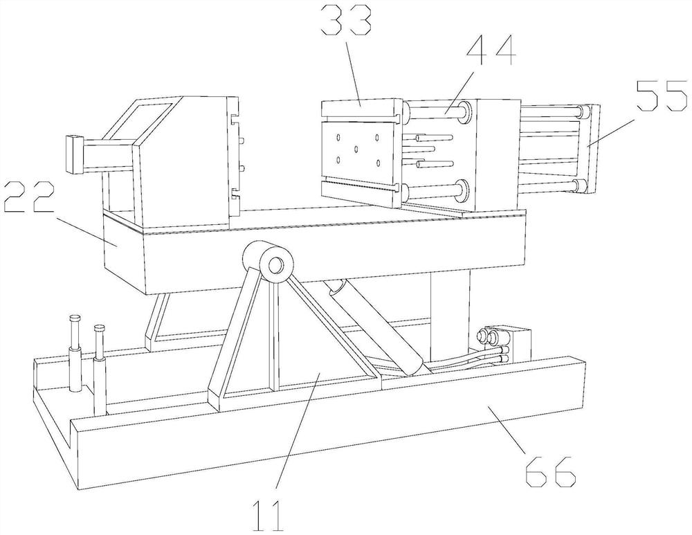
[0032] as attached figure 1 to attach Image 6 Shown:

[0033] The present invention provides a metal type gravity casting mold, the structure of which includes a support plate 11, a heavy pressure table 22, a heavy pressure plate 33, a support rod 44, a stripping plate 55, and a base 66. The support plate 11 is welded to the upper surface of the base 66, The end of the support plate 11 away from the base 66 is connected to the weight table 22 , the strut 44 is connected to the weight plate 33 , and the stripping plate 55 penetrates inside the weight plate 33 and is movably connected.

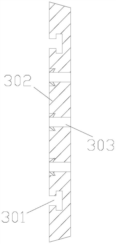
[0034] The heavy pressure plate 33 includes a notch 301 , a main block 302 , and a through opening 303 , the notch 301 and the main block 302 are an integrated structure, and the through opening 303 runs through the main block 302 .

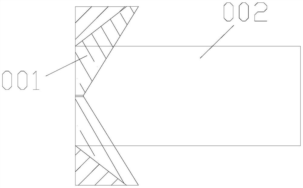
[0035] Wherein, the port 303 includes a one-way block 001 and an air port 002, the one-way block 001 is connected to the air port 002, the one-way block 001 is ...

Embodiment 2

[0042] as attached Figure 7 to attach Figure 9 Shown:

[0043] Wherein, the solid block 111 includes a connecting body s01, a hard body s02, an adhesive layer s03, and a stretching body s04. The adhesive layer s03 is attached to the outer surface of the connecting body s01, and the connecting body s01 is fixed on the outside of the hard body s02. On the surface, the end of the connecting body s01 away from the hard body s02 is connected to the exhibition body s04, the rubber layer s03 is made of rubber material and has a certain toughness, the hard body s02 is a triangular structure, and the hard body s02 fixes the overall hard force, the connecting body s01 is connected between the force receiving part and the fixed part, and plays the role of connecting and buffering, and the extending body s04 expands according to the external force.

[0044] Wherein, the connecting body s01 includes a ball core 511, a total support body 512, and a rubber extension body 513. The ball co...


PUM


Abstract

The invention discloses a metal mold gravity casting mold. The metal mold gravity casting mold structurally comprises a supporting plate, a heavy pressing table, a heavy pressing plate, a supporting rod, a demolding plate and a base, the supporting plate is welded to the upper surface of the base, the end, away from the base, of the supporting plate is connected with the heavy pressing table, the supporting rod is connected with the heavy pressing plate, and the demolding plate penetrates through the interior of the heavy pressing plate and is movably connected with the heavy pressing plate; and a main block for a pressed part of an object can die-cast the object, a one-way block can keep the hard force of the one-way block, a force bearing point is fixed through a force fixing block, so that an external object can be better dredged, the external objec is wrapped through a soft strip, separation corners on the two sides can keep certain hard force, and when the object is subjected to gravity die-casting, an opening is reversely closed to prevent the opening from being squeezed in, when an extension board is reversely demoulded, an extension body is stretched and extended, and a spherical core is connected between a main supporting body and an extension colloid to play a buffering role, so that when the connection part is stressed, fixing can be carried out when fixation is needed, and extension can be timely carried out when extension is needed.

Description

technical field [0001] The invention belongs to the field of moulds, and more specifically relates to a metal type gravity casting mould. Background technique [0002] The metal mold is placed on the gravity casting equipment, and through the pressure of the casting equipment, it is deformed in the limited space between the pressing of the object and fills the entire space. [0003] Based on above-mentioned inventor's discovery, existing metal type gravity casting mold mainly exists following several deficiencies, such as: [0004] When the gravity casting platen presses the object, the metal-shaped object will be forced into the demoulding hole under the double pressure, thereby damaging its shape and even being stuck in the hole. [0005] Therefore need to propose a kind of metal type gravity casting mould. Contents of the invention [0006] In order to solve the above-mentioned technology, when the gravity casting pressure plate presses the object, the metal-shaped ob...

Claims


Application Information

Patent Timeline
IPC IPC(8): B22D17/22
CPCB22D17/22B22D17/2236
Inventor 吴伟
Owner 上海路动网络科技有限公司
Features
  • Generate Ideas
  • Intellectual Property
  • Life Sciences
  • Materials
  • Tech Scout
  • Unparalleled Data Quality
  • Higher Quality Content
  • 60% Fewer Hallucinations
Learn More