A turning fixture for flange blind plate

A flange blind plate and turning technology, which is applied in the direction of turning equipment, turning equipment, manufacturing tools, etc., can solve the problems that affect the feeding of turning tools, and the three-jaw chuck cannot meet the needs of clamping flange blind plate blanks, etc. , to achieve the effect of improving turning precision, reducing clamping error and improving machining precision

A flange blind plate and turning technology, which is applied in the direction of turning equipment, turning equipment, manufacturing tools, etc., can solve the problems that affect the feeding of turning tools, and the three-jaw chuck cannot meet the needs of clamping flange blind plate blanks, etc. , to achieve the effect of improving turning precision, reducing clamping error and improving machining precision

CN112872394BActive Publication Date: 2022-07-26济南江华锻铸机械有限公司

Image

  • A turning fixture for flange blind plate
  • A turning fixture for flange blind plate
  • A turning fixture for flange blind plate

Examples


Embodiment Construction

[0039] Attached to the following Figure 1-6 This application will be described in further detail.

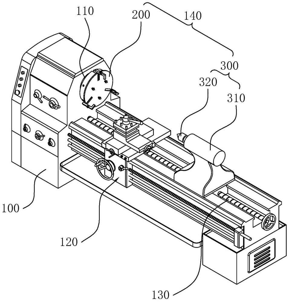
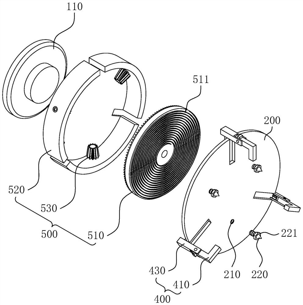
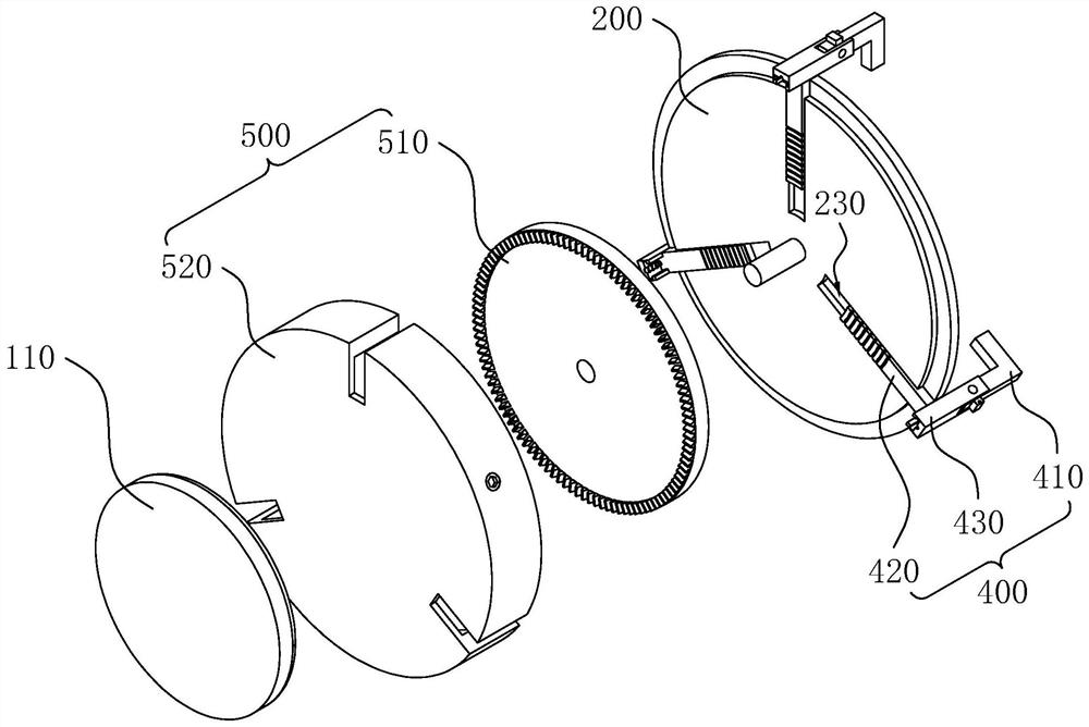
[0040] The embodiment of the present application discloses a turning fixture for a flange blind plate. refer to figure 1 and figure 2 , the turning fixture 140 of the flange blind plate includes a base plate 200 as a basic support, a first pressing mechanism 300 and a second pressing mechanism 400 for pressing the blank. The base plate 200 is disposed on the main shaft 110 of the lathe, the first edge mechanism is disposed on the frame 100 of the lathe, and the second pressing mechanism 400 is disposed on the base plate 200 .

[0041] refer to figure 1 and figure 2 , the cross section of the base plate 200 is arranged in a circle, and the base plate 200 is coaxially and fixedly connected to the main shaft 110 of the lathe through a coupling. The main shaft 110 of the lathe is mostly coaxially fixedly connected with a three-jaw chuck through a coupling. In other embodi...


PUM


Abstract

The application relates to a turning fixture for a flanged blind plate, and relates to the technical field of metal processing equipment. It includes a base plate, a first pressing mechanism and a second pressing mechanism. The vertebra is rotatably connected to the tailstock, the tail vertebra is coaxially arranged with the base plate, the base plate is coaxially fixedly connected to the main shaft of the lathe, and the second pressing mechanism includes a clamping claw which is slidably connected to the base plate. In this application, when processing the outer peripheral surface of the blank, the base plate and the tail cone are used to clamp the blank, so that the outer peripheral surface of the blank is completely exposed; when processing the boss of the blank, the base plate and the clamping jaw are used to clamp the blank. In this way, the axial part of the blank part will be completely exposed, which is convenient for the feeding of the turning tool.

Description

technical field [0001] The present application relates to the field of metal processing equipment, in particular to a turning fixture for flanged blind plates. Background technique [0002] Blind flange, also known as blind flange, the real name is blind plate, is a form of flange, which can be understood as a flange without a hole in the middle. The functions of the flange blind plate: one is to block the end of the pipeline, and the other is to easily remove the sundries in the pipeline during maintenance. As far as the blocking effect is concerned, it has the same function as the head and the pipe cap, but the head cannot be disassembled, and the flange blind plate is fixed with bolts, which is very convenient to disassemble. [0003] refer to Image 6 , the flange blind plate 600 includes a plate body 610 and a boss 620 coaxially arranged on the plate body 610. During the transfer process, the boss 620 plays the role of separating the flange blind plate 600, so that the...

Claims


Application Information

Patent Timeline
26 Jul 2022
Publication
CN112872394B
IPC
B23B31/16; B23B31/103; B23B5/00
CPC
B23B31/16; B23B31/103; B23B5/00
Inventors
菅宗玉; 菅宗耀