Unlock instant, AI-driven research and patent intelligence for your innovation.

Robot grabbing system based on depth vision and using method thereof

A technology of deep vision and robotics, applied in the field of robotics, can solve the problems of lubricating lag, easy to pollute the environment, and slide rails cannot be lubricated, and achieve the effect of easy adjustment and avoiding scanning blind spots

Active Publication Date: 2021-06-01
山东润江智控科技有限公司
View PDF6 Cites 0 Cited by
  • Summary
  • Abstract
  • Description
  • Claims
  • Application Information

AI Technical Summary

Problems solved by technology

Install the depth vision sensor at the front end of the robot tool at 3 to 5 cm. This installation method is to avoid the impact of various harsh environments on site, but this installation method will cause problems: the robot’s running track is limited, It must run in a direction perpendicular to the structured light of the depth vision sensor, and the measurement is susceptible to changes in the attitude of the industrial robot itself
[0003] In addition, the slide rail of the walking axis (seventh axis) of the robot system has to withstand high-speed and high-pressure friction back and forth during the working process. Effective lubrication for it is a very important maintenance method to ensure the normal operation of the slide rail. Currently, there are There are a large number of lubricating devices in the technology, but there are still some problems in the process of using them. For example, when lubricating and maintaining, the lubricating oil is usually added manually at regular intervals, and the oil film on the surface of the slide rail is mostly observed with the naked eye. For maintenance, this method is likely to cause lubrication lag problems, resulting in the slide rails not being lubricated in time and effectively, resulting in greater wear, and the manual lubrication method is time-consuming and labor-intensive. In addition, the existing device exerts pressure on the entire box surface , and then ensure that the oil can be fully overflowed, but this method is not easy to control the oil output speed and oil output, and it is prone to excessive overflow of lubricating oil, which is a waste of cost and easy to pollute the environment

Method used


Image

  • Robot grabbing system based on depth vision and using method thereof
  • Robot grabbing system based on depth vision and using method thereof
  • Robot grabbing system based on depth vision and using method thereof

Examples


Embodiment Construction

[0030]Embodiments of the present invention are described in detail below, examples of which are shown in the drawings, wherein the same or similar reference numerals designate the same or similar elements or elements having the same or similar functions throughout. The embodiments described below by referring to the figures are exemplary only for explaining the present invention and should not be construed as limiting the present invention.

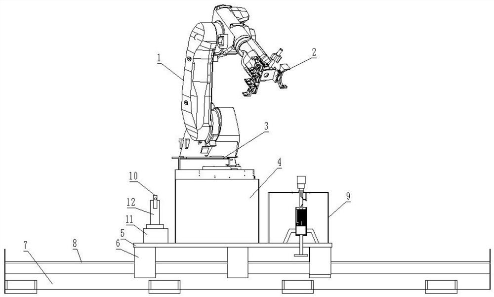
[0031] Such as Figure 1-7 As shown, a robot grasping system based on depth vision proposed in this embodiment includes a robot body, and the robot body includes a mechanical arm 1 with a gripper 2 connected to the mechanical arm 1 and a rotating seat 3 connected to the bottom of the mechanical arm 1 , the bottom of the rotating seat 3 is connected with a base 4, and a seventh shaft is arranged under the base 4, and the seventh shaft includes a ground rail 7, and a slide rail 8 is arranged on the ground rail 7, and the slide rail 8 is sli...


PUM


Abstract

The invention discloses a robot grabbing system based on depth vision and a using method thereof. The robot grabbing system comprises a mechanical arm, a clamping jaw is connected to the mechanical arm, a rotating seat is connected to the bottom of the mechanical arm, a base is connected to the bottom of the rotating seat, a seventh shaft is arranged below the base and comprises a ground rail, and a sliding rail is arranged on the ground rail; and the sliding rail is slidably connected with a sliding block, the top of the sliding block is fixedly connected with a supporting table, and the supporting table is connected with a driving mechanism. The supporting table is connected with the base; and the supporting table is further provided with a depth vision sensor which is connected to an elevator, and the bottom of the elevator is connected with the supporting table. A lubricating system is arranged on the supporting table. According to the system, the depth vision sensor and the robot are mounted on the same supporting table, so that a scanning blind area caused by posture change of the robot is effectively avoided; and the lubricating system is ingenious in structural design, the relative position change between a piston and a plunger is achieved through the change of a guide groove, and then oil extraction and lubrication can be completed.

Description

technical field [0001] The invention relates to the technical field of robots, in particular to a robot grasping system based on depth vision and a method for using the same. Background technique [0002] In the field of robot applications, especially when moving in one direction for a long distance, because the running trajectory is too long to teach, it is necessary to calculate the theoretical trajectory of the robot in advance, and then perform a small-scale correction of the robot's running pose during the running process. At present, the solution to this problem is usually to install a depth vision sensor on the robot tool, and project the structured light of the depth vision sensor on the front end of the robot tool at 3-5cm. The difference between the current positions of the robot tools corrects the robot trajectory. Install the depth vision sensor at the front end of the robot tool at 3 to 5 cm. This installation method is to avoid the impact of various harsh envi...

Claims


Application Information

Patent Timeline
IPC IPC(8): B25J19/00B25J5/02B25J13/08
CPCB25J19/0062B25J5/02B25J13/08
Inventor 刘建勇李书振李鑫韩玉冰
Owner 山东润江智控科技有限公司
Features
  • R&D
  • Intellectual Property
  • Life Sciences
  • Materials
  • Tech Scout
  • Unparalleled Data Quality
  • Higher Quality Content
  • 60% Fewer Hallucinations
Learn More