
Injection molding equipment for plug injection molding

A technology of injection molding and injection equipment, applied in the direction of coating, etc., can solve the problems of lack of positioning of plug terminals, easy skew of plug terminals, etc.

Active Publication Date: 2021-06-01
台州腾标电子有限公司
View PDF8 Cites 1 Cited by
  • Summary
  • Abstract
  • Description
  • Claims
  • Application Information

AI Technical Summary

Problems solved by technology

[0004] In view of the above-mentioned related technologies, the inventor believes that there is a defect that the plug terminals lack positioning after the plug terminals are put into the lower cavity, and the plug terminals are easily skewed after injection molding is completed.

Method used


Image

  • Injection molding equipment for plug injection molding
  • Injection molding equipment for plug injection molding
  • Injection molding equipment for plug injection molding

Examples


Embodiment 1

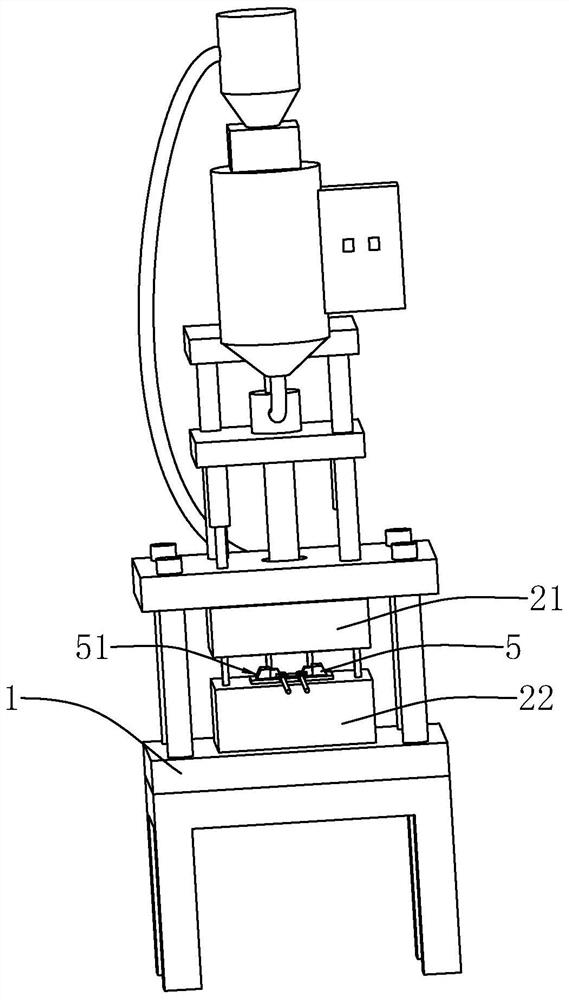
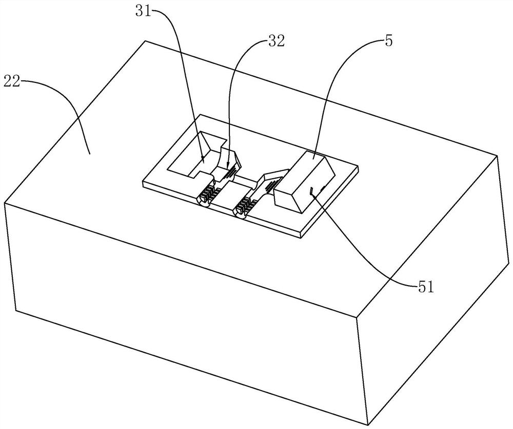
[0037] refer to figure 1 and figure 2 , including machine base 1, terminal holder 5 and injection molding device, injection molding device includes lower mold 22, upper mold 21, driving mechanism and injection mechanism, both driving mechanism and injection mechanism are installed on the machine base 1, and upper mold 21 is fixed Installed on the driving mechanism, the lower mold 22 is installed on the support 1 and is located below the upper mold 21 . The upper mold 21 is provided with a connected upper cavity and an upper relief cavity, and the lower mold 22 is provided with a lower cavity 32 and a lower relief cavity 31, and the lower cavity 32 and the upper cavity are combined into a cable for placing cables. The injection molding cavity, the lower relief cavity 31 and the upper relief cavity are combined into a placement cavity for placing the terminal holder 5. The terminal holder 5 is provided with an insertion hole 51 for inserting a plug terminal, and the insertion...

Embodiment 2

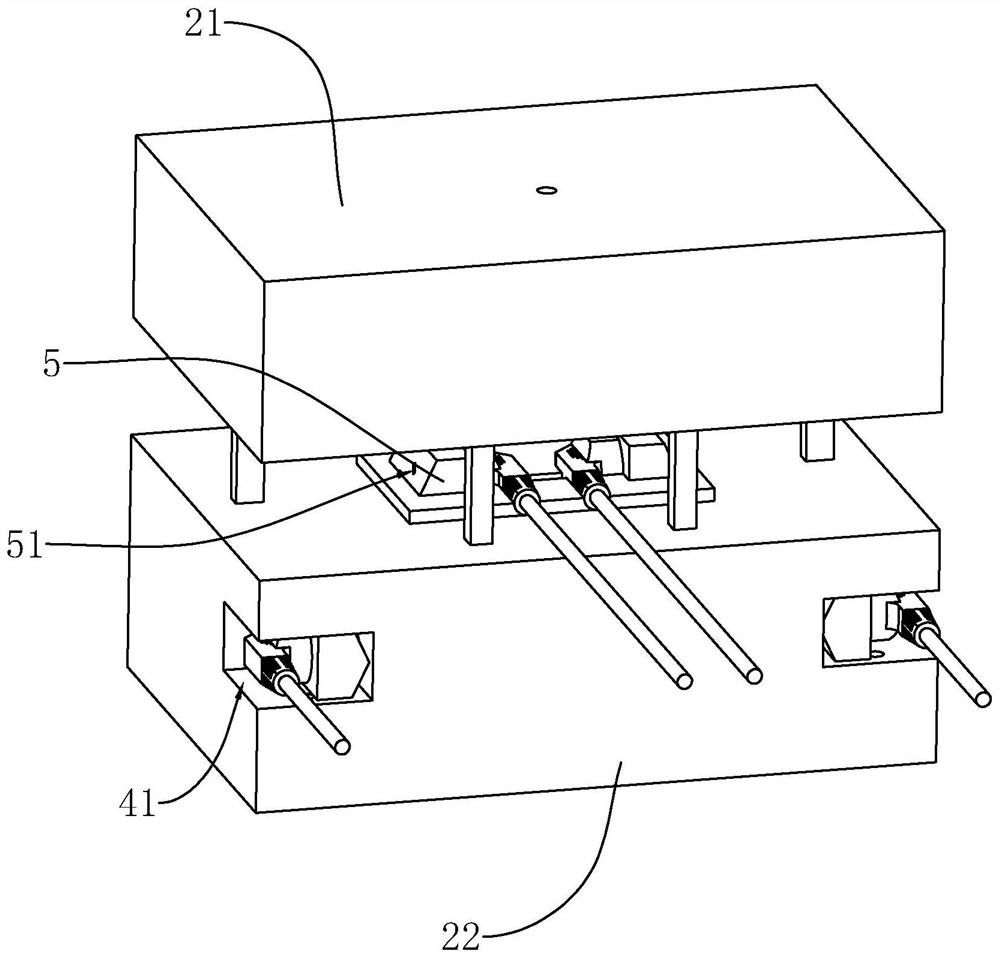
[0040] refer to image 3 and Figure 4The difference between this embodiment and Embodiment 1 is that the lower mold 22 is provided with a positioning cavity 41, a sliding cavity 421, a lift hole 422 and an extension hole 43, and the sliding cavity 421 and the positioning cavity 41 pass through the extension hole 43 The lifting hole 422 communicates with the sliding cavity 421 and communicates with the outside world. The positioning cavity 41 is used for placing the terminal holder 5 .

[0041] refer to Figure 4 and Figure 5 The lower mold 22 is also provided with an ejector plate 64 and a sliding mechanism for sliding the ejector plate 64. The sliding mechanism includes a lifting rod 61, a sliding rod 62 and an abutment assembly, and the abutment assembly includes a fixed plate 63 and an abutment assembly. Connect spring 65. The lifting rod 61 is fixedly connected to the upper mold 21 and can extend into the sliding cavity 421 through the lifting hole 422 . One side o...


PUM


Abstract

The invention relates to injection molding equipment for plug injection molding, and relates to the field of injection molding equipment. The injection molding equipment comprises a terminal clamping base, a machine base and an injection molding device. The injection molding device comprises an upper mold, a lower mold, a driving mechanism and a material injection mechanism, wherein the lower mold is fixedly installed on a rack, the driving mechanism is fixedly installed on the rack and connected with the upper mold to drive the upper mold to ascend and descend, the upper mold is provided with an upper receding cavity and an upper cavity which are communicated with each other, the lower mold is provided with a lower receding cavity and a lower cavity, the upper cavity and the lower cavity are spliced to form an injection molding cavity, the upper receding cavity and the lower receding cavity are spliced to form a placing cavity for placing the terminal clamping base, the terminal clamping base is provided with a jack for inserting a plug terminal, and the jack penetrates through the terminal clamping base. The injection molding equipment has the effect of reducing the skew probability of the plug terminal.

Description

technical field [0001] The present application relates to the field of injection molding equipment, in particular to an injection molding equipment for plug injection molding. Background technique [0002] Wire plugs are very common and necessary electrical devices in life and production. After the wires are connected in production, the wire plugs need to be injected with plastic to wrap and hide the connecting wires, which is safer and more convenient to use. [0003] The existing plug injection molding process is that the operator puts the terminal in the lower cavity of the lower mold, and then the upper mold is lowered to fit the lower mold, and the upper cavity of the upper mold is connected with the lower cavity of the lower mold. Flatten to form injection cavity. The injection molding mechanism injects molten plastic into the injection cavity to complete injection molding. [0004] With regard to the above-mentioned related technologies, the inventor believes that t...

Claims


Application Information

Patent Timeline
Patent Type & Authority Applications(China)
IPC IPC(8): B29C45/14B29C33/12B29C45/26
CPCB29C45/14065B29C45/14639B29C45/2602
Inventor 夏文波
Owner 台州腾标电子有限公司
Learn More