Supercharge Your Innovation With Domain-Expert AI Agents!

Feeding mechanism

A feeding mechanism and hopper technology, applied in the field of automatic feeding mechanism, can solve the problems of unsuitable feeding and workpiece wear, and achieve the effect of reducing wear

Active Publication Date: 2021-06-01
东莞市起源自动化科技有限公司
View PDF6 Cites 0 Cited by
  • Summary
  • Abstract
  • Description
  • Claims
  • Application Information

AI Technical Summary

Problems solved by technology

[0002] In the past, the cylindrical workpiece with a central hole was usually fed through a vibrating plate, but if the vibrating plate is used to feed, the workpiece will continue to rub against the vibrating plate and the workpiece, which will bring a certain amount of wear to the workpiece and have relatively high requirements for appearance. The workpiece is not suitable for feeding with a vibrating plate, so it is urgent to design a feeding mechanism that can reduce the wear on the surface of the workpiece

Method used


Image

  • Feeding mechanism
  • Feeding mechanism
  • Feeding mechanism

Examples


Embodiment Construction

[0020] The present invention will be further described below in conjunction with accompanying drawing:

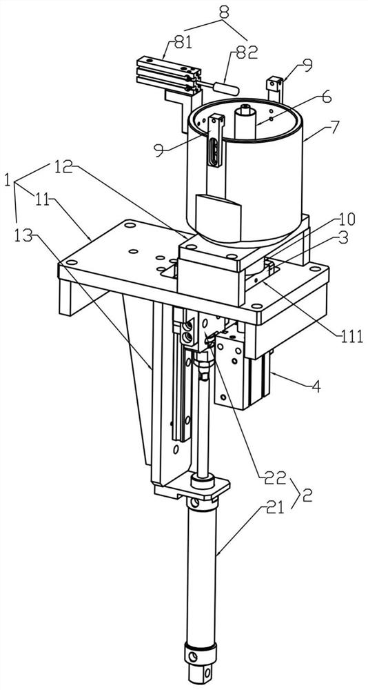
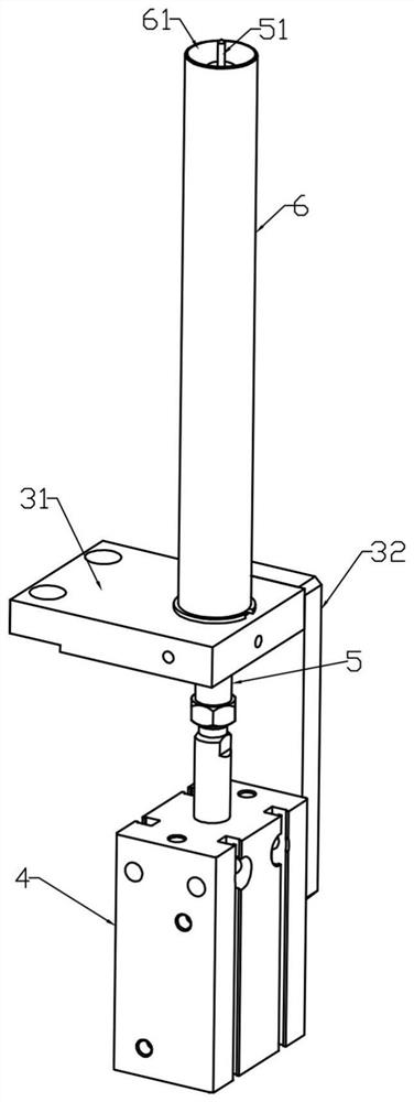
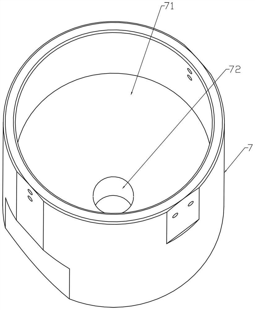
[0021] Such as Figure 1-4 As shown, a feeding mechanism includes a mounting frame 1, a Z-axis driving device 2, a connecting frame 3, a push rod driving device 4, a push rod 5, a cylinder body 6, a hopper 7, a material pushing device 8 and a sensor 9; The Z-axis driving device 2 is installed on the mounting frame 1 and the power output end is connected with the connecting frame 3 to drive the connecting frame 3 to move up and down; the hopper 7 is fixed on the mounting frame 1 and is located above the connecting frame 3; the cylinder body 6 is vertical It is directly fixed on the connecting frame 3 and can be pierced from the bottom of the hopper 7 to the top of the hopper 7; the upper end of the cylinder 6 is provided with a groove body 61; the push rod 5 can be installed in the cylinder 6 up and down; The upper end of the push rod 5 is provided with a positioning column...


PUM


Abstract

The invention provides a feeding mechanism. The feeding mechanism comprises a mounting frame, a Z-axis driving device, a connecting frame, a push rod driving device, a push rod, a barrel, a hopper, a pushing device and a sensor. The Z-axis driving device is mounted on the mounting frame, and the power output end of the Z-axis driving device is connected with the connecting frame to drive the connecting frame to move up and down. The hopper is fixed on the mounting frame and is positioned above the connecting frame. The barrel is vertically fixed on the connecting frame and can penetrate from the bottom of the hopper to be arranged above the hopper. A groove body is arranged at the upper end of the barrel. The push rod is mounted in the barrel in a manner of moving up and down. A positioning column is arranged at the upper end of the push rod. The push rod driving device is mounted on the connecting frame, and the power output end of the push rod driving device is connected with the bottom of the push rod. The pushing device and the sensor are fixed to one side of the upper portion of the hopper, and it is shown that abrasion to workpieces can be reduced in the feeding process.

Description

technical field [0001] The invention relates to the technical field of automatic feeding mechanism, in particular to a feeding mechanism for a cylindrical workpiece with a central hole. Background technique [0002] In the past, the cylindrical workpiece with a central hole was usually fed through a vibrating plate, but if the vibrating plate is used to feed, the workpiece will continue to rub against the vibrating plate and the workpiece, which will bring a certain amount of wear to the workpiece and have relatively high requirements for appearance. The workpiece is not suitable for feeding with a vibrating plate, so it is urgent to design a feeding mechanism that can reduce the wear on the surface of the workpiece. Contents of the invention [0003] The purpose of the present invention is to provide a feeding mechanism to solve the problems mentioned in the background art. [0004] In order to achieve the above object, the present invention provides the following techni...

Claims


Application Information

Patent Timeline
IPC IPC(8): B65G43/08B65G47/82B65G47/18B65G47/90
CPCB65G43/08B65G47/82B65G47/18B65G47/90B65G2203/042
Inventor 李启元覃裕林王宁吕永强邓先逸
Owner 东莞市起源自动化科技有限公司
Features
  • R&D
  • Intellectual Property
  • Life Sciences
  • Materials
  • Tech Scout
  • Unparalleled Data Quality
  • Higher Quality Content
  • 60% Fewer Hallucinations
Learn More