Supercharge Your Innovation With Domain-Expert AI Agents!

Turnover device and method suitable for elastic deflection beam

A technology of elastic deflection and turning frame, which is applied in the direction of transportation and packaging, load hanging components, etc., can solve the problems of beam structure size difference, failure to recover, beam deformation, etc., to reduce the difficulty of turning over, simple structure, Avoid the effect of shock

Pending Publication Date: 2021-06-01
CHINA RAILWAY BAOJI BRIDGE GRP
View PDF0 Cites 0 Cited by
  • Summary
  • Abstract
  • Description
  • Claims
  • Application Information

AI Technical Summary

Problems solved by technology

During the turnover operation of the steel track beam, due to the high rigidity of the track beam, it is only necessary to install the lifting lug device on the track beam, and the track beam can be turned over by hanging the lifting lug through the lifting equipment. However, for some tracks with small self-rigidity and easy deformation The beam is equipped with a lifting lug device. When it is hoisted, the beam body will deform under the influence of its own weight, or even yield.

Method used


Image

  • Turnover device and method suitable for elastic deflection beam
  • Turnover device and method suitable for elastic deflection beam
  • Turnover device and method suitable for elastic deflection beam

Examples


Embodiment 1

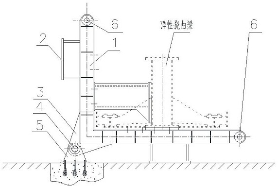
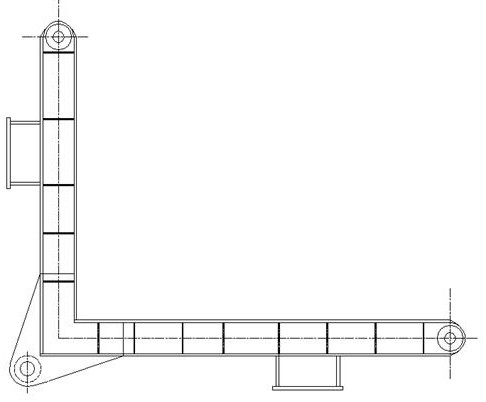
[0016] Example 1: refer to the attached Figure 1-8 . A turning device suitable for elastic flexural beams is composed of an L turning frame 1, a supporting pier 2, an anchoring pin shaft lug 3, an anchoring pin shaft 4, and a fixed seat 5. The anchoring pin shaft lug 3 and the L turning frame are composed of 1 is connected at the root, the anchor pin 3 is hinged to the fixed seat 5 through the anchor pin 4, the fixed seat 5 is fixed on the ground as a fixed rotation point, and the support pier 2 is connected to the frame body of the L turning frame respectively. The two connecting ends of the L turning frame are respectively hoisting holes 6 .

Embodiment 2

[0017] Example 2: On the basis of Example 1, a method for turning over an elastically deflected beam, one lifting point of the hoisting device is connected to the first hoisting hole 6 in the L turning frame 1, and another lifting point of the hoisting device and The second hoisting hole 6 in the L turning frame 1 is connected. Through the action of the lifting equipment, the first hoisting hole 6 is raised sideways, and the second hoisting hole 6 is sidely lowered to realize the beam body 90 0 Turn over, and then be supported by the support pier 2 on the L turning frame; change the position of the turning device, the first hoisting hole 6 side in the L turning frame 1 descends, the second hoisting hole 6 side rises, the L turning frame is turned in place, and then the Supported by the support pier 2 on the L turning frame.


PUM


Abstract

The invention relates to a turnover device and method suitable for an elastic deflection beam. The turnover device and method suitable for the elastic deflection beam can enable a track beam not to deform and not to yield when the track beam which is small in rigidity and easy to deform is turned over, the turnover device is composed of an L-shaped turnover frame, supporting piers, an anchoring pin shaft lug, an anchoring pin shaft and a fixed base, and the anchoring pin shaft lug is connected with the root of the L-shaped turnover frame; and the anchoring pin shaft lug is hinged to the fixed base through the anchoring pin shaft, the fixed base is fixed to the ground to serve as a fixed rotation point, and the supporting piers are connected with a frame body of the L-shaped turnover frame. The turnover device and method have the advantages that firstly, stable turnover of the elastic deflection beam is achieved, the supporting piers are arranged to support a beam body, and cantilever parts at the two sides of the beam body are protected; secondly, the rigidity of the beam body in the turnover process is improved by arranging a plurality of lifting turnover points, and the size of the beam body is easy to control; and thirdly, the turnover problem of an overweight beam body is solved, and the turnover of a large-tonnage beam body can be realized by virtue of lifting equipment with smaller tonnage by virtue of a lever principle through the arrangement of the ground anchor type fixed base.

Description

technical field [0001] The invention relates to a turning device and method suitable for an elastic flexural beam, which can turn a track beam with low rigidity and easy deformation during turning operation without deformation and yielding of the track beam, belonging to a track beam. Turn over device manufacturing field. Background technique [0002] In the assembly and welding of steel track beams, the beam body can only be assembled and welded after several times of turning over due to structural constraints. During the turning operation of the steel track beam, due to the high rigidity of the track beam, it is only necessary to set the lifting lug device on the track beam, and the lifting lug can be suspended by the lifting equipment to realize the turning of the track beam. However, for some tracks with low rigidity and easy deformation For the beam, the lifting lug device is set on the beam. When lifting, the beam body deforms under the influence of its own weight, an...

Claims


Application Information

Patent Timeline
IPC IPC(8): B66C1/22B66C13/08B66C13/06
CPCB66C1/22B66C13/06B66C13/08
Inventor 余锋牛均宽张宁
Owner CHINA RAILWAY BAOJI BRIDGE GRP
Features
  • R&D
  • Intellectual Property
  • Life Sciences
  • Materials
  • Tech Scout
  • Unparalleled Data Quality
  • Higher Quality Content
  • 60% Fewer Hallucinations
Learn More