Installation joint of steel frame and prefabricated inner partition wall

A steel frame and inner partition wall technology, applied to walls, building components, buildings, etc., can solve problems such as error adaptability, achieve the effects of improving assembly rate, reducing on-site working time, and convenient installation

Pending Publication Date: 2021-06-01
TONGJI UNIV ARCHITECTURAL DESIGN INST GRP CO LTD
View PDF0 Cites 0 Cited by
  • Summary
  • Abstract
  • Description
  • Claims
  • Application Information

AI Technical Summary

Problems solved by technology

However, the connection between the current steel frame and the prefabricated partition wall is still a difficult point in structural design, and the adaptability of the installation error between the steel frame and the prefabricated partition wall is also a problem that needs attention

Method used


Image

  • Installation joint of steel frame and prefabricated inner partition wall
  • Installation joint of steel frame and prefabricated inner partition wall
  • Installation joint of steel frame and prefabricated inner partition wall

Examples


Embodiment

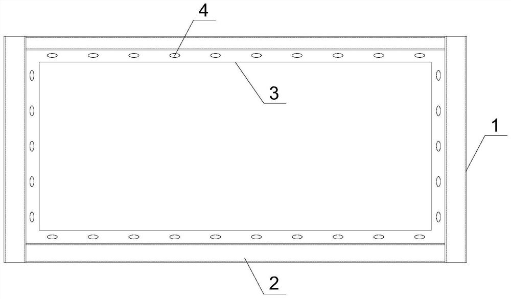
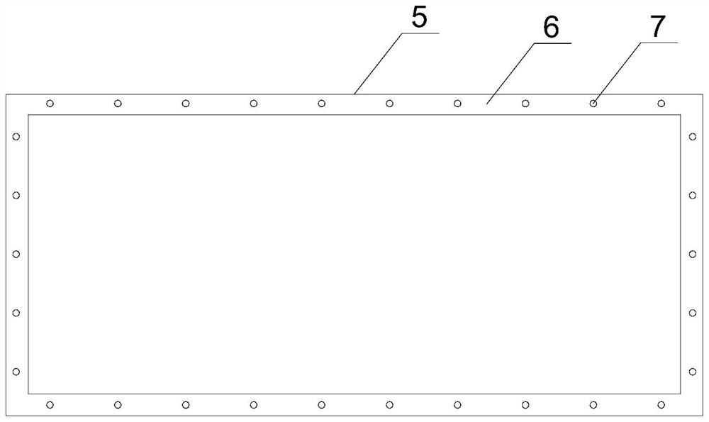
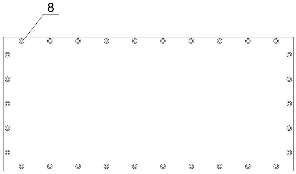
[0028] like Figure 1~6 As shown, the present invention relates to an installation node between a steel frame and a prefabricated inner partition wall. The steel frame involved in the present invention includes a frame column 1, a frame beam 2 and a frame edge gusset plate 3, and the frame edge gusset plate 3 is a rectangular frame structure , the two frame beams 2 are symmetrically arranged on the outer surfaces of the two symmetrical frames of the frame edge gusset plate 3 (such as the top of the upper frame and the bottom of the lower frame), and the length is the same as the length of the corresponding frame of the frame edge gusset plate 3; the two frames The column 1 is symmetrically arranged on the outer surfaces of the other two symmetrical frames of the frame edge gusset plate 3 (for example, the outer wall of the left frame and the outer wall of the right frame), and the end of the frame column 1 is flush with the edge of the frame beam 2 . A plurality of oval holes ...


PUM


Abstract

The invention relates to an installation joint of a steel frame and a prefabricated inner partition wall. The steel frame is provided with a frame edge joint plate (3), a plurality of first bolt holes are distributed in the side faces of all frames of the frame edge joint plate (3), inner clamping grooves (6) used for installing the side faces of all the frames of the frame edge joint plate (3) are formed in the edge of the wall face of one side of the prefabricated inner partition wall, a plurality of second bolt holes are evenly formed in the inner clamping grooves (6) at equal intervals in a penetrating mode, and the set positions of the second bolt holes correspond to the set positions of the first bolt holes. Compared with the prior art, the installation joint has the advantages of shortening the field working time, being convenient to install, higher in adaptability to installation errors and the like.

Description

technical field [0001] The invention relates to the technical field of steel frame structures, in particular to an installation node between a steel frame and a prefabricated inner partition wall. Background technique [0002] Prefabricated decoration is a new form of decoration construction that transports all parts required for decoration to the decoration site for combined installation after the factory produces them. The construction is simpler and more convenient, which can greatly improve the construction efficiency of the decoration site, and ensure that the construction site is more tidy and beautiful, and will not produce too much decoration material waste. It is a more green and environmentally friendly form of decoration construction. With the vigorous advocacy of prefabricated buildings in recent years, steel frame structures, as a kind of prefabricated buildings, do not have on-site cast work, the installation speed is faster, and the construction quality is eas...

Claims


Application Information

Patent Timeline
IPC IPC(8): E04B2/82E04B2/74
CPCE04B2/7407E04B2/82
Inventor 吴水根吕兆华闵杰
Owner TONGJI UNIV ARCHITECTURAL DESIGN INST GRP CO LTD
Why Eureka
Try Eureka