Valve stroke and switching time measuring circuit, device, system and method

A technology for measuring circuit and valve stroke, applied in the field of measurement, can solve the problems of difficulty in finding the measurement position, low measurement efficiency, affecting measurement work, etc., to achieve the effect of convenient installation and simple operation

Pending Publication Date: 2020-11-10
CHINA GENERAL NUCLEAR POWER OPERATION +2
View PDF6 Cites 0 Cited by
  • Summary
  • Abstract
  • Description
  • Claims
  • Application Information

AI Technical Summary

Problems solved by technology

In the process of measuring these two parameters, the valve needs to be switched on and off many times, and it needs the cooperation of many maintenance personnel to complete it, and the measurement efficiency is low.
[0004] In addition, due to the complex location of the on-site valve installation space and the surrounding installation of pipelines or other equipment, the maintenance personnel need to be close to the...

Method used


Image

  • Valve stroke and switching time measuring circuit, device, system and method
  • Valve stroke and switching time measuring circuit, device, system and method
  • Valve stroke and switching time measuring circuit, device, system and method

Examples


Embodiment Construction

[0053] In order to have a clearer understanding of the technical features, purposes and effects of the present invention, the specific implementation manners of the present invention will now be described in detail with reference to the accompanying drawings.

[0054] It should be noted that the terms "first", "second", "third" and so on are only for the convenience of describing the technical solution, and should not be understood as indicating or implying the relative importance or implicitly indicating the indicated technical features quantity. Those of ordinary skill in the art can understand the specific meanings of the above terms in the present invention according to specific situations.

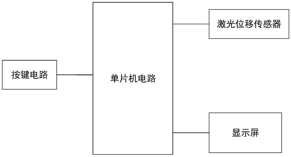
[0055] see figure 2 , is a structural schematic diagram of Embodiment 1 of the valve stroke and switching time measurement circuit of the present invention.

[0056] Such as figure 2 As shown, the valve stroke and switching time measurement circuit includes a single-chip microcom...


PUM


Abstract

The invention relates to a valve stroke and switching time measuring circuit, device, system and method. The measuring circuit comprises a single-chip microcomputer circuit, a key circuit, a laser displacement sensor and a display screen. The laser displacement sensor is connected with the single-chip microcomputer circuit through a signal line. The key circuit and the display screen are connectedwith the single-chip microcomputer circuit. The single-chip microcomputer circuit is used for calculating the valve stroke and the time of the valve opening and closing process according to changes of output signals of the laser displacement sensor. The keying circuit serves as an input module and is used for starting or closing the measuring circuit and adjusting the laser displacement sensor; the display screen is used for displaying the calculation result of the single-chip microcomputer circuit. According to the technical scheme, the measurement precision and the measurement efficiency are improved; the measurement difficulty and the risk that maintainers mistakenly touch equipment are reduced; the field working time is shortened, the distance between maintainers and the pipeline in the measurement process is increased, and the exposure dose of the maintainers is reduced.

Description

technical field [0001] The invention relates to the field of measurement technology, in particular to a valve stroke and switching time measurement circuit, device, system and method. Background technique [0002] as attached figure 1 As shown, in order to achieve remote control, the valve is usually designed with an electric or pneumatic drive mechanism. The drive mechanism drives the valve stem and disc to move up and down to realize the switch of the valve, thereby remotely controlling the on-off of the medium in the pipeline. For straight-stroke valves such as electric gate valves, pneumatic switching valves, and pneumatic control valves, it is usually required to measure the stroke and switching time of the valve after the relevant maintenance process of this type of valve is completed, so as to verify the valve stroke and switching time (opening time) after maintenance. Time and closing time) two important performance parameters are still within the design range, thus...

Claims


Application Information

Patent Timeline
IPC IPC(8): G01D21/02
CPCG01D21/02
Inventor 梅增胜彭松贤陈明谭志周丽丽常松苏龙龙辜彬
Owner CHINA GENERAL NUCLEAR POWER OPERATION
Why Eureka
Try Eureka