Water pressure protector for water purifier

A technology for water purifiers and protectors, which is applied in the direction of pipes/pipe joints/fittings, mechanical equipment, pipe components, etc., and can solve problems such as leakage and failure of water purifiers

Inactive Publication Date: 2021-06-01
宁波凌宏商贸有限公司
View PDF0 Cites 0 Cited by
  • Summary
  • Abstract
  • Description
  • Claims
  • Application Information

AI Technical Summary

Problems solved by technology

[0005] The purpose of the present invention is to provide a water pressure protector for water purifiers that can provide effective protection for most traditional water purifiers that are prone to leakage and failure when they are used.

Method used


Image

  • Water pressure protector for water purifier
  • Water pressure protector for water purifier
  • Water pressure protector for water purifier

Examples


Embodiment 1

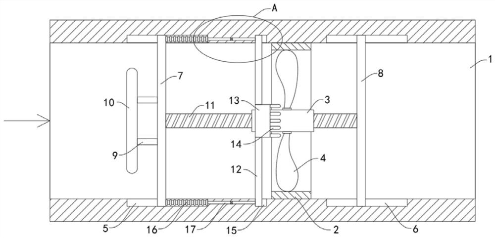
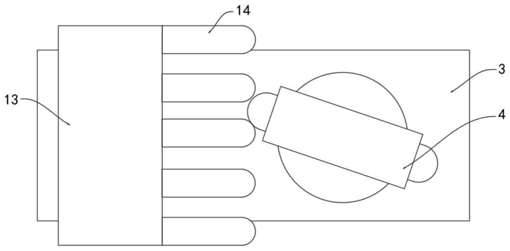
[0025] Such as Figure 1-3 As shown, a water pressure protector for a water purifier includes a horizontal pipe 1, and the two ends of the horizontal pipe 1 are respectively connected to the water inlet of the water purifier and the water inlet of tap water, and a rotating fan 2 is fixedly installed in the horizontal pipe 1. The rotating fan 2 includes a rotating shaft 3 and a plurality of fan blades 4, and the plurality of fan blades 4 are rotatably connected to the outer wall of the rotating shaft 3 through a coil spring.

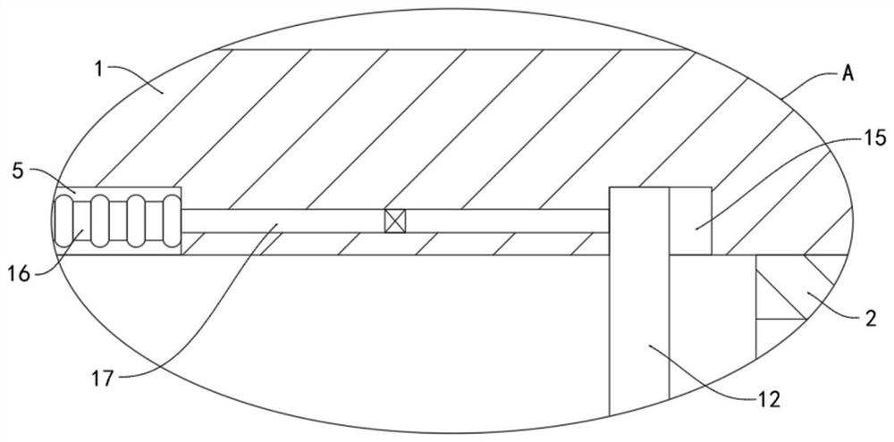
[0026] The horizontal pipe 1 is provided with a front fixing groove 5 and a rear fixing groove 6 respectively located at the front and rear ends of the rotating fan 2, and the front fixing groove 5 and the rear fixing groove 6 are slidingly connected with a front fixing net plate 7 and a rear fixing net plate 8 respectively. The front end of the fixed net plate 7 is fixedly connected with a water blocking plate 10 through a plurality of connecting rods 9 ...

Embodiment 2

[0035] Such as Figure 4-5 As shown, the difference between this embodiment and Embodiment 1 is that the peripheral side wall of the rotating fan 2 is fixedly connected with a fixed block 18 extending to the inner side wall of the horizontal tube 1, and the inner side wall of the horizontal tube 1 is provided with a fixed block. 18 is matched with the buffer groove 19, and the buffer spring 20 is fixedly connected between the fixed block 18 and the inner wall of the buffer groove 19, and the rotating fan 2 is slidably connected with the inner wall of the horizontal pipe 1.

[0036] In this embodiment, when the water pressure in the horizontal pipe 1 is relatively large, and the rotation of the entire rotating fan 2 causes a reverse driving force on the water flow, the rotating fan 2 subjected to greater resistance will move a certain distance backward in the buffer tank 19, and then It will move back and forth in the buffer groove 19 under the elastic action of multiple buffer...


PUM


Abstract

The invention belongs to the field of water purifiers, and particularly relates to a water pressure protector for a water purifier. The water pressure protector for the water purifier comprises a horizontal pipe, wherein a rotating fan is fixedly mounted in the horizontal pipe; the rotating fan comprises a rotating shaft and a plurality of fan blades; the plurality of fan blades are rotatably connected with the outer side wall of the rotating shaft through coil springs; a front fixing groove and a rear fixing groove which are located in the front end and the rear end of the rotating fan respectively are formed in the horizontal pipe; a front fixing net plate and a rear fixing net plate are slidably connected into the front fixing groove and the rear fixing groove respectively; and the front end of the front fixing net plate is fixedly connected with a water baffle through a plurality of connecting rods. According to the water pressure protector for the water purifier provided by the invention, through the arrangement of a buffer groove and buffer springs, when the water pressure in the horizontal pipe is large and the rotation of the whole rotating fan causes reverse pushing force to a water flow, and the rotating fan subjected to large resistance can move backwards by a certain distance in the buffer groove and then can move back and forth in the buffer groove under the elastic action of the multiple buffer springs, so that the thrust of the water flow can be converted into elastic force and consumed, and the impact of the water flow on the rotating fan can be effectively relieved.

Description

technical field [0001] The invention belongs to the field of water purifiers, in particular to a water pressure protector for a water purifier. Background technique [0002] With the continuous improvement of living standards, more and more people begin to pay attention to their health. Installing water purifiers at home is one of the more common phenomena. Water purifiers have gradually begun to go to thousands of households and continuously improve people's quality of life. . [0003] Most household water purifiers are directly connected in series to the tap water pipes when in use, and the water pressure flow rate of tap water is generally relatively unstable, prone to irregular fluctuations, while the seals of traditional water purifiers and some low-voltage switches All are prone to leakage and failure in a high-pressure environment, which will not only cause waste of water resources, but also easily affect the normal use of the water purifier, and it is difficult to a...

Claims


Application Information

Patent Timeline
Patent Type & Authority Applications(China)
IPC IPC(8): F16L55/02
CPCF16L55/02
Inventor 刘金三
Owner 宁波凌宏商贸有限公司
Why Eureka
Try Eureka