Dehumidifier

A technology for dehumidifiers and fuselages, which is applied in the direction of household heating, heating and ventilation covers/covers, lighting and heating equipment, etc., and can solve the problem of uncompact internal structure of the fuselage, unreasonable distribution of internal components, and space utilization Low-level problems, to achieve the effect of facilitating transportation and storage, rational and compact arrangement of original parts, and improving utilization rate

Pending Publication Date: 2021-06-01
GD MIDEA AIR-CONDITIONING EQUIP CO LTD
View PDF0 Cites 0 Cited by
  • Summary
  • Abstract
  • Description
  • Claims
  • Application Information

AI Technical Summary

Problems solved by technology

For example, in traditional dehumidifiers, the distribution of internal components is unreasonable, which makes the internal structure of the fuselage not compact and the utilization rate of space is low

Method used


Image

  • Dehumidifier
  • Dehumidifier
  • Dehumidifier

Examples


Embodiment Construction

[0055] The following will clearly and completely describe the technical solutions in the embodiments of the present invention with reference to the accompanying drawings in the embodiments of the present invention. Obviously, the described embodiments are only part of the embodiments of the present invention, not all of them. Based on the embodiments of the present invention, all other embodiments obtained by persons of ordinary skill in the art without creative efforts fall within the protection scope of the present invention.

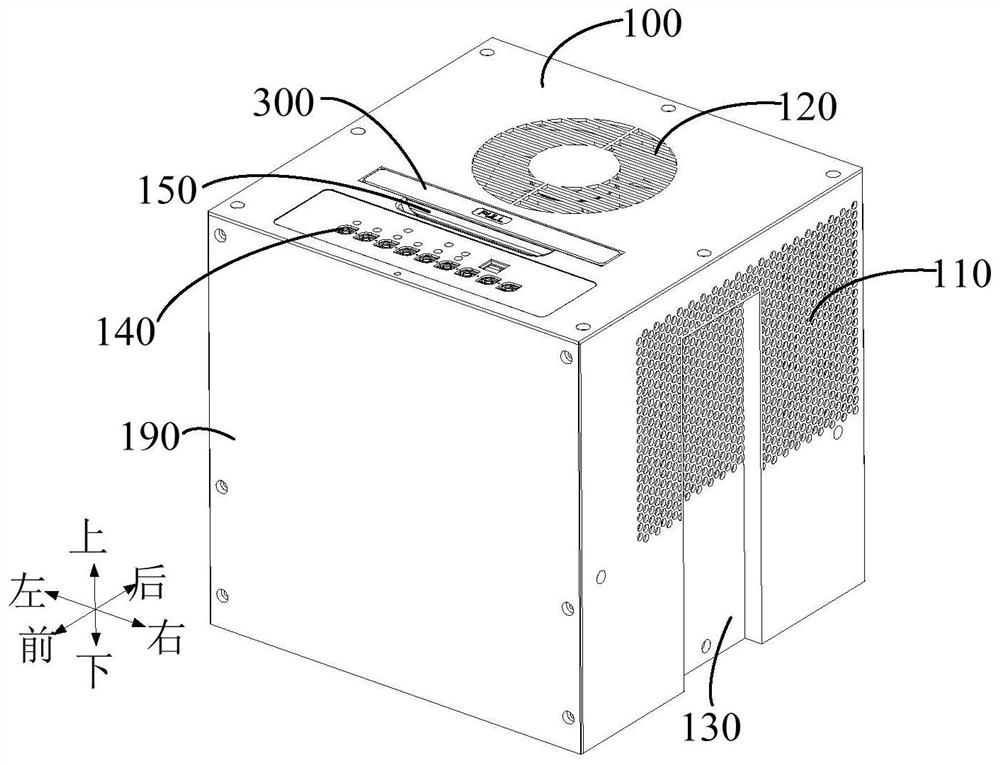
[0056] It should be noted that all directional indications (such as up, down, left, right, front, back...) in the embodiments of the present invention are only used to explain the relationship between the components in a certain posture (as shown in the accompanying drawings). Relative positional relationship, movement conditions, etc., if the specific posture changes, the directional indication will also change accordingly.

[0057] In addition, the ...


PUM


Abstract

The invention discloses a dehumidifier which comprises a machine body. The machine body comprises a shell provided with an air inlet and an air outlet, a condenser arranged in the shell, an evaporator arranged in the shell, a centrifugal fan arranged in parallel with the evaporator and the condenser, a water pan and a compressor; the air outlet direction of the centrifugal fan faces the air outlet; the water pan is arranged under the condenser and the evaporator and connected with the centrifugal fan, and the interior of the shell is divided into a centrifugal air channel and a mounting cavity; and the compressor is arranged in the mounting cavity. According to the technical scheme, the compactness of a dehumidification structure can be better improved.

Description

technical field [0001] The invention relates to the technical field of dehumidifiers, in particular to a dehumidifier. Background technique [0002] With the improvement of people's living standards, people's requirements for indoor living environment are also getting higher and higher. As a device for adjusting air humidity, people's requirements for dehumidifiers have also increased. For example, in traditional dehumidifiers, the distribution of internal components is unreasonable, which makes the internal structure of the fuselage not compact and the utilization rate of space is low. Contents of the invention [0003] The main purpose of the present invention is to provide a dehumidifier, aiming to provide a dehumidifier with a reasonable internal structure layout, so as to improve the compactness of the internal structure and the utilization rate of the space. [0004] In order to achieve the above object, the dehumidifier proposed by the present invention includes a...

Claims


Application Information

Patent Timeline
Patent Type & Authority Applications(China)
IPC IPC(8): F24F3/14F24F13/20
CPCF24F3/14F24F13/20F24F2003/1446
Inventor 李伟明邢志钢
Owner GD MIDEA AIR-CONDITIONING EQUIP CO LTD
Why Eureka
Try Eureka