Plate cleaning equipment

A technology for cleaning equipment and plates, which is applied in the direction of dust removal, cleaning methods and utensils, cleaning methods using tools, etc., and can solve problems such as unclean plate cleaning, a large amount of cleaning oil, and complicated processes

Pending Publication Date: 2021-06-04
济南融和创自动化设备有限公司
View PDF1 Cites 3 Cited by
  • Summary
  • Abstract
  • Description
  • Claims
  • Application Information

AI Technical Summary

Problems solved by technology

The device is complex in process, uses many rollers, requires a large amount of cleaning oil during the cleaning process, and has high investment and use costs. In addition, during the cleaning process, the moving direction of the plate and the brush is parallel, and the brush is prone to generate static electricity. The follow-up cleaning is not thorough, and the plate cleaning is not clean, resulting in low cleaning efficiency and affecting the subsequent stamping process

Method used


Image

  • Plate cleaning equipment
  • Plate cleaning equipment
  • Plate cleaning equipment

Examples


Embodiment 1

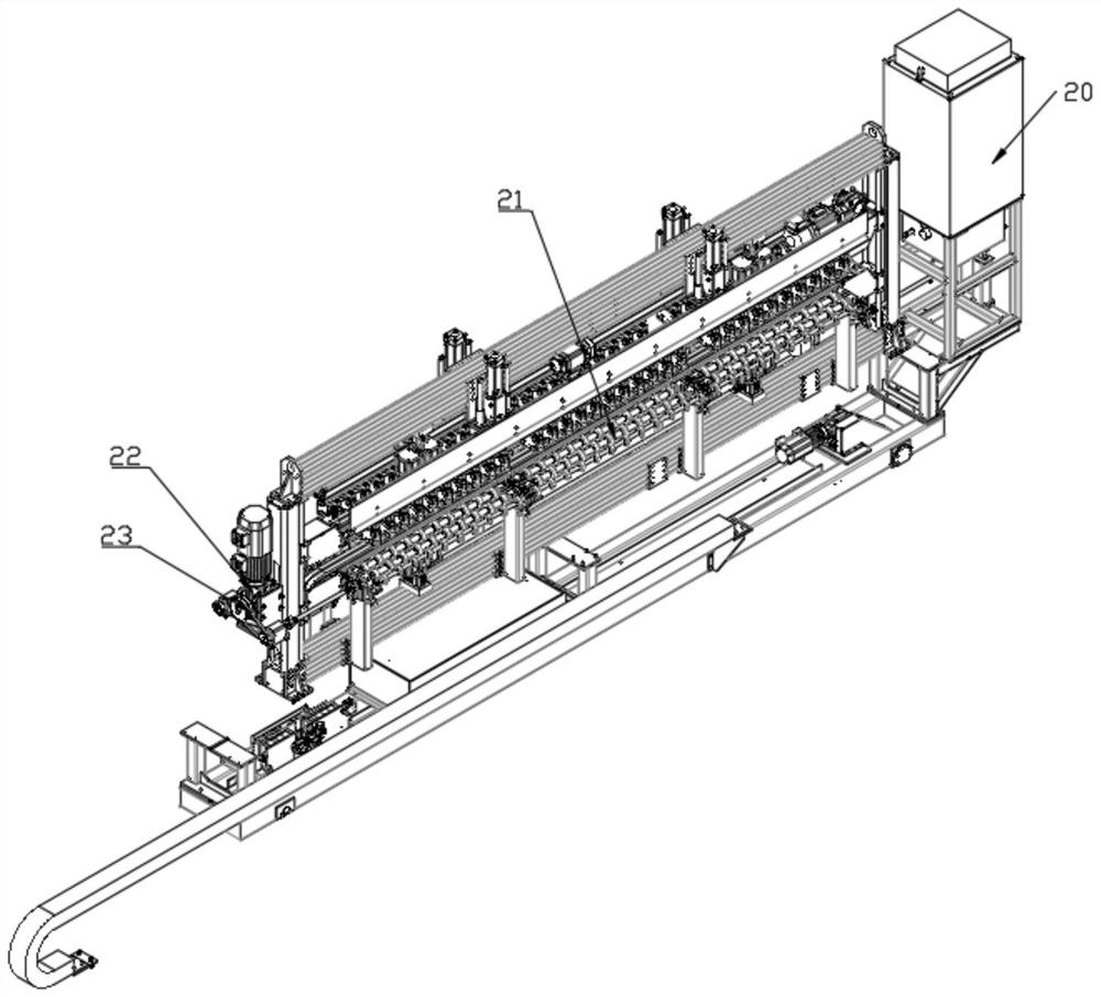
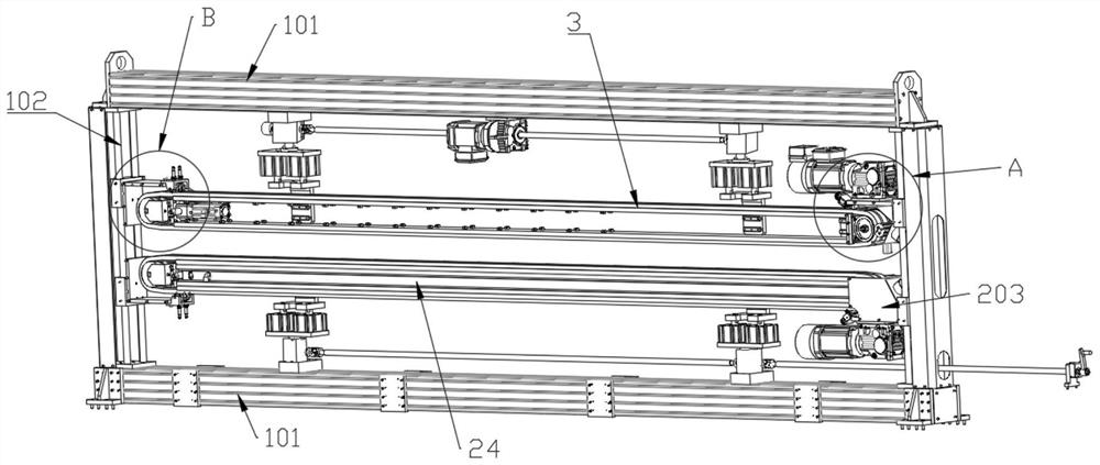
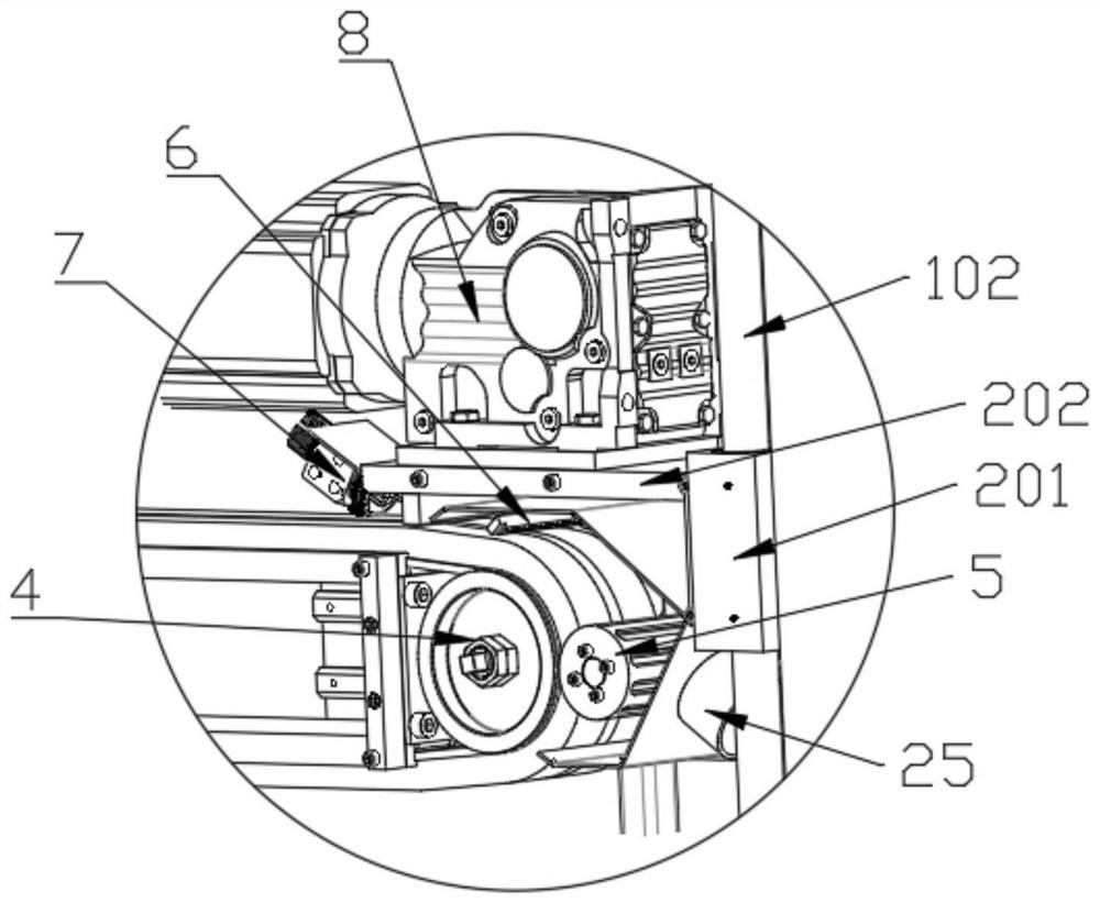
[0032] Such as Figure 1-Figure 6 The plate cleaning equipment shown includes a frame, and the frame includes two upper and lower beams 101, the left and right ends of the two beams 101 are supported by polished rods 102, and the polished rods 102 are provided with two sets of parallel corresponding support seats through linear bearing sliding , the support seat includes an L-shaped plate 202, a sliding seat 201, and two vertical plates 203 on the left and right. Fixed connection.

[0033] A belt roller 4 is provided between the two vertical plates 203 inside the support base, and a fixed plate 24 is provided between the two corresponding belt rollers 4 on the left and right sides. There are two brush belts 3 up and down, and the belt roller 4 on the right is provided with a brush driving mechanism 8 , and the brush driving mechanism 8 is fixed on the outer end surface of the L-shaped plate 202 .

[0034] The output end of the hairbrush driving mechanism 8 and the rotating s...

Embodiment 2

[0040] Such as Figure 1-Figure 6 The plate cleaning equipment shown includes a frame, and the frame includes two upper and lower beams 101, the left and right ends of the two beams 101 are supported by polished rods 102, and the polished rods 102 are provided with two sets of parallel corresponding support seats through linear bearing sliding , the support seat includes an L-shaped plate 202, a sliding seat 201, and two vertical plates 203 on the left and right. Fixed connection.

[0041] A belt roller 4 is provided between the two vertical plates 203 inside the support base, and a fixed plate 24 is provided between the two corresponding belt rollers 4 on the left and right sides. There are two brush belts 3 up and down, and the belt roller 4 on the right is provided with a brush driving mechanism 8 , and the brush driving mechanism 8 is fixed on the outer end surface of the L-shaped plate 202 .

[0042] The output end of the hairbrush driving mechanism 8 and the rotating s...

Embodiment 3

[0048] Such as Figure 1-Figure 6 The plate cleaning equipment shown includes a frame, and the frame includes two upper and lower beams 101, the left and right ends of the two beams 101 are supported by polished rods 102, and the polished rods 102 are provided with two sets of parallel corresponding support seats through linear bearing sliding , the support seat includes an L-shaped plate 202, a sliding seat 201, and two vertical plates 203 on the left and right. Fixed connection.

[0049] A belt roller 4 is provided between the two vertical plates 203 inside the support base, and a fixed plate 24 is provided between the two corresponding belt rollers 4 on the left and right sides. There are two brush belts 3 up and down, and the belt roller 4 on the right is provided with a brush driving mechanism 8 , and the brush driving mechanism 8 is fixed on the outer end surface of the L-shaped plate 202 .

[0050] The output end of the hairbrush driving mechanism 8 and the rotating s...


PUM


Abstract

The invention discloses plate cleaning equipment, and relates to the technical field of plate cleaning. The plate cleaning equipment comprises a rack, the inner side of the rack is slidably provided with two groups of supporting seats corresponding with each other in parallel, the inner sides of the supporting seats are provided with belt rollers, a fixing plate is arranged between every two corresponding belt rollers on the left and right sides, and the left and right belt rollers are rotatably connected through brush belts correspondingly; the two brush belts are arranged in the vertical direction, brush driving mechanisms are arranged on the belt rollers on the right side, rotary scrapers are arranged on the outer sides of the belt rollers on the right side, an outer cover is arranged on the outer side of each rotary scraper, air suction openings are formed in the outer covers; and the air suction openings are connected with an air suction filtering system, and conveying systems are arranged on the front sides and the rear sides of the belt rollers. According to the plate cleaning equipment, dust on the surface of a plate is removed through the brush belts, then the rotary scrapers loosen the dust to fall, the air suction filtering system sucks the dust away, air blowing holes blow the dust to the air suction openings, the dust is sucked more thoroughly, no roller is arranged in the whole equipment, the production cost is greatly reduced, and the operation cost is low.

Description

technical field [0001] The invention relates to the technical field of plate cleaning, in particular to plate cleaning equipment with lower cost and better cleaning effect. Background technique [0002] At present, for passenger car products, customers have high requirements on the appearance quality. Therefore, it is very important to ensure the quality of automobile outer panels in stamping production, and the surface cleaning quality of the sheet has the greatest impact on the appearance of stamping parts. [0003] The Chinese utility model patent with the application number "201920437126.3" discloses a multifunctional plate cleaning machine, which includes a plate, a cleaning device, and a workbench; there are several sets of heating devices, oil spray nozzles, sponge rollers, and spiral brushes on the workbench roller; the heating device is located on the left side of the cleaning device, and there are several guide rollers below it; the plate moves from the upper end o...

Claims


Application Information

Patent Timeline
Patent Type & Authority Applications(China)
IPC IPC(8): B08B1/02B08B13/00B08B15/04
CPCB08B1/002B08B1/007B08B1/02B08B13/00B08B15/04
Inventor 戴荣聚戴明佑王超
Owner 济南融和创自动化设备有限公司
Why Eureka
Try Eureka