Injection molding machine nozzle cleaning device

A cleaning device and injection molding machine technology, applied in the field of injection molding machines, can solve the problems of pinching, inconvenient, and affecting injection molding, and achieve the effect of easy insertion and shortening the time for cleaning nozzles

Inactive Publication Date: 2021-06-04
马鞍山河谷照阳信息科技咨询有限公司
View PDF0 Cites 0 Cited by
  • Summary
  • Abstract
  • Description
  • Claims
  • Application Information

AI Technical Summary

Problems solved by technology

[0003] However, after the injection molding is completed, the workers often find that there is a large amount of solidified plastic attached to the inner wall of the nozzle, which causes the nozzle space to become smaller after the nozzle has been used for a long time, and is eventually blocked, which affects the later injection molding. The main reason for the blockage is the flow of thermoplastic plastic Poor performance, the plastic solidifies on the inner wall of the nozzle after shutdown
In order to clean the residual plastic in the nozzle, people usually use a musket (a fire-breathing device) to increase the temperature of the nozzle, and then use pliers to clamp the plastic leaking from the nozzle and pull it out; If it is out, you need to use a hook to hook it out, which is very inconvenient

Method used


Image

  • Injection molding machine nozzle cleaning device
  • Injection molding machine nozzle cleaning device

Examples


Embodiment

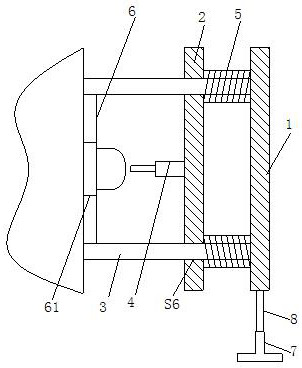
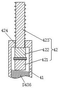
[0021] Such as figure 1 , figure 2 As shown, the injection molding machine nozzle cleaning device described in this embodiment is used to clean the injection molding machine nozzle; it includes a bottom plate 1, a movable plate 2, a limit rod 3, a cleaning mechanism 4 and a first elastic member 5; the movable plate 2 is set On the side of the bottom plate 1 close to the nozzle, the first elastic member 5 is arranged between the bottom plate 1 and the movable plate 2, and is always in a compressed state. One end of the limit rod 3 is fixedly connected to the bottom plate 1, and the other end is connected to the The through hole on the movable plate 2 makes the movable plate 2 slide along the limit rod 3 and maintains a parallel state with the base plate 1 all the time; The second elastic part 43 between the base 41 and the telescopic part 42 is always in a compressed state. The telescopic part 42 includes a fixing part 421 , a limiting part 422 and a heating part 423 . Fixed...


PUM


Abstract

The invention provides an injection molding machine nozzle cleaning device which is used for cleaning an injection molding machine nozzle. The injection molding machine nozzle cleaning device comprises a bottom plate, a movable plate, position-limiting rods, a cleaning mechanism and first elastic pieces, wherein the movable plate is arranged on the side, close to the nozzle, of the bottom plate, the first elastic pieces are arranged between the bottom plate and the movable plate and are always in a compressed state, one ends of the position-limiting rods are fixedly connected with the bottom plate, the other ends of the position-limiting rods penetrate through through holes in the movable plate, the movable plate is made to slide along the position-limiting rods and be always kept parallel to the bottom plate, the cleaning mechanism comprises a hollow base, a telescopic piece connected with the base in a sleeving mode and a second elastic piece which is arranged between the base and the telescopic piece and is always in a compressed state, the telescopic piece comprises a fixing piece, a position-limiting piece and a heating piece, the fixing piece is fixedly connected with the second elastic piece, the position-limiting piece is rotatably connected with the fixing piece, the heating piece is fixedly connected with the end, away from the fixing piece, of the position-limiting piece, screw threads are arranged on the outer surface of the heating piece, and a position-limiting hole is formed in the base.

Description

technical field [0001] The invention relates to the technical field of injection molding machines, in particular to a nozzle cleaning device for injection molding machines. Background technique [0002] Plastic injection molding machine, also known as injection molding machine or injection machine, is a device that injects or injects thermoplastics into the injection cavity of the injection mold, and uses the different shapes of the injection cavity in the injection mold to form plastic products of different shapes. The injection molding machine includes a feeding device, a heating device, a plastic melting furnace and a nozzle mechanism. The feeding device is located above the plastic melting furnace. The heating device, the inlet of the nozzle mechanism communicates with the discharge port of the plastic melting furnace, wherein the nozzle mechanism includes a spray barrel, a nozzle arranged on the spray barrel, and a piston arranged in the spray barrel for applying pressu...

Claims


Application Information

Patent Timeline
Patent Type & Authority Applications(China)
IPC IPC(8): B29C45/24
CPCB29C45/24
Inventor 李琳
Owner 马鞍山河谷照阳信息科技咨询有限公司
Why Eureka
Try Eureka