
Head support system for operation with anesthesia

A technology of supporting system and head, applied in the field of medical equipment, can solve the problems of ventilation obstacle, discount, unfavorable operation of the operator, etc., and achieve the effect of good contact affinity and good contact.

Inactive Publication Date: 2018-11-20
SICHUAN LIZHI JIUCHUANG INTPROP OPERATION CO LTD
View PDF0 Cites 0 Cited by
  • Summary
  • Abstract
  • Description
  • Claims
  • Application Information

AI Technical Summary

Problems solved by technology

In previous operations, the patient’s head was often turned to one side, which is not conducive to the operator’s operation and the anesthesiologist’s respiratory management. With the improvement of medical equipment, a prone position head frame has been developed for prone position surgery. It is found in clinical practice that although the current prone position head frame can meet the needs of surgical operations, it has the following disadvantages: first, the existing prone position head frame is poorly adjustable, and it is difficult to fit patients with all face shapes. And it is easy to cause compression damage to the eyes, mouth and nose of the patient; secondly, because the threaded tube of the anesthesia machine is long and heavy, it is easy to take out the threaded tube or compress or discount it to one side during the general anesthesia process, which is difficult for the anesthetist to observe. It brings many difficulties and operation, and it is also very inconvenient to use; in addition, some patients may cause their head to swing due to mental tension and reflex adverse reactions during anesthesia, which may lead to ventilation obstruction or threaded tube falling off

Method used


Image

  • Head support system for operation with anesthesia
  • Head support system for operation with anesthesia
  • Head support system for operation with anesthesia

Examples


Embodiment 1

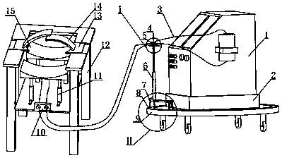
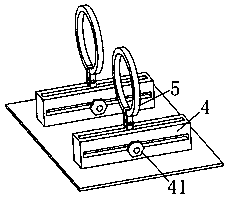
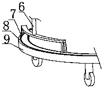
[0034] as attached figure 1 , attached figure 2 , attached image 3 In this embodiment shown, a head support system for anesthesia surgery includes an anesthesia machine 1, a deck 2, a threaded tube 3, a slide rail 4, a fastener 41, a clip 5, a telescopic rod 6, and a rolling frame body 7 , an annular concave rail 8, a base 9, a threaded tube limit hole 10, a mandibular support assembly 11, a bracket body 12, a clamping plate 13, a buckle 14, a forehead support assembly 15, an anesthesia machine 1 is installed with a threaded tube 3, a threaded tube 3. The breathing circuit is formed by connecting the angle adjustment bracket and the fixed bracket to the mouth of the human body. The angle adjustment bracket includes a base 9, a deck 2 and a bracket assembly. The deck 2 is used to install the anesthesia machine 1. The bracket assembly rolls relative to the base 2, the relative position of the bracket assembly and the fixed bracket can be adjusted, and then the installation a...


PUM


Abstract

The invention relates to the field of medical equipment, in particular to a head support system for an operation with anesthesia. The head support system comprises an angle adjusting bracket and a fixing bracket, wherein the angle adjusting bracket comprises a base, a clamp seat and a bracket assembly, the bracket assembly and the clamp seat are arranged on the base, the bracket assembly is in rolling connection with the base and used for adjusting the mounting angle of a screw tube, and the clamp seat is in rotational connection with the base and used for adjusting the mounting angle of an anesthesia machine; the fixing bracket comprises a rolling bracket body, a support device and a clamp device, the support device is used for adjusting the head support position to be proper, the clamp device is used for head positioning. The head support system is simple in structure and convenient to operate, the screw tube can be prevented from being brought out or being compressed and folded to one side in an anesthesia process, the condition of ventilation disturbance or falling off of the screw tube due to the fact that the head of a patient probably swings in the anesthesia process can beavoided, and the head support system is suitable for a prone position operation.

Description

technical field [0001] The invention relates to the field of medical equipment, in particular to a head support system for anesthesia operations. Background technique [0002] In orthopedic or surgical operations, there are many operations that require patients to take a prone position, such as posterior cervical surgery, lumbar posterior surgery, and intracranial surgery. In previous operations, the patient’s head was often turned to one side, which is not conducive to the operator’s operation and the anesthesiologist’s respiratory management. With the improvement of medical equipment, a prone position head frame has been developed for prone position surgery. It is found in clinical practice that although the current prone position head frame can meet the needs of surgical operations, it has the following disadvantages: first, the existing prone position head frame is poorly adjustable, and it is difficult to fit patients with all face shapes. And it is easy to cause compr...

Claims


Application Information

Patent Timeline
IPC IPC(8): A61G13/12A61M16/01
CPCA61G13/1215A61G13/126A61G2200/325A61M16/01
Inventor 张羽袁迎春
Owner SICHUAN LIZHI JIUCHUANG INTPROP OPERATION CO LTD
Learn More