Textile machine part automatic lubricating device

An automatic lubrication, textile machine technology, applied in the direction of engine lubrication, engine components, lubricating parts, etc., can solve problems such as troublesome cleaning, general oil tank sealing, lubricating oil overflow, etc., and achieve the effect of preventing accidental overflow

Inactive Publication Date: 2021-06-04
成都滔洽未电子商务有限公司
View PDF3 Cites 0 Cited by
  • Summary
  • Abstract
  • Description
  • Claims
  • Application Information

AI Technical Summary

Problems solved by technology

[0002] Natural fibers or chemical fibers are processed into various mechanical equipment required for textiles. In a broad sense, textile machinery also includes chemical machinery for the production of chemical fibers. Textile equipment is the production means and material basis of the textile industry. Its technical level, quality and manufacturing cost, It is directly related to the development of the textile industry, but in the existing small textile equipment, a small oil pot is still used to lubricate the equipment. The oil inlet of the oil pot is generally sealed, and sometimes it may cause the lubricant to overflow and flow It is too cumbersome to clean on the pot body, and the amount of oil dripped into the lubricating oil is generally based on the user's experience. The amount of dripping oil is not easy to control, so that the lubrication effect of the textile equipment is not good. Intuitive observation of oil intake

Method used


Image

  • Textile machine part automatic lubricating device
  • Textile machine part automatic lubricating device
  • Textile machine part automatic lubricating device

Examples


Embodiment Construction

[0021] The following will clearly and completely describe the technical solutions in the embodiments of the present invention with reference to the accompanying drawings in the embodiments of the present invention. Obviously, the described embodiments are only some, not all, embodiments of the present invention. Based on the embodiments of the present invention, all other embodiments obtained by persons of ordinary skill in the art without making creative efforts belong to the protection scope of the present invention.

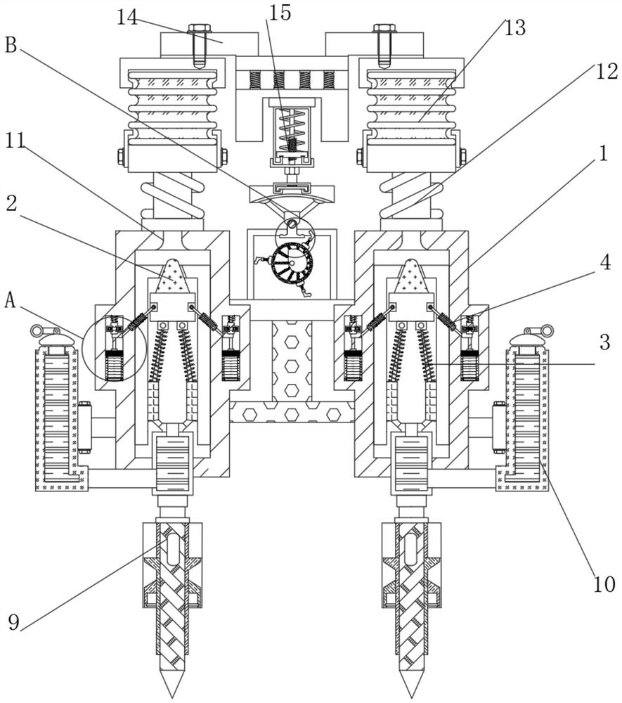
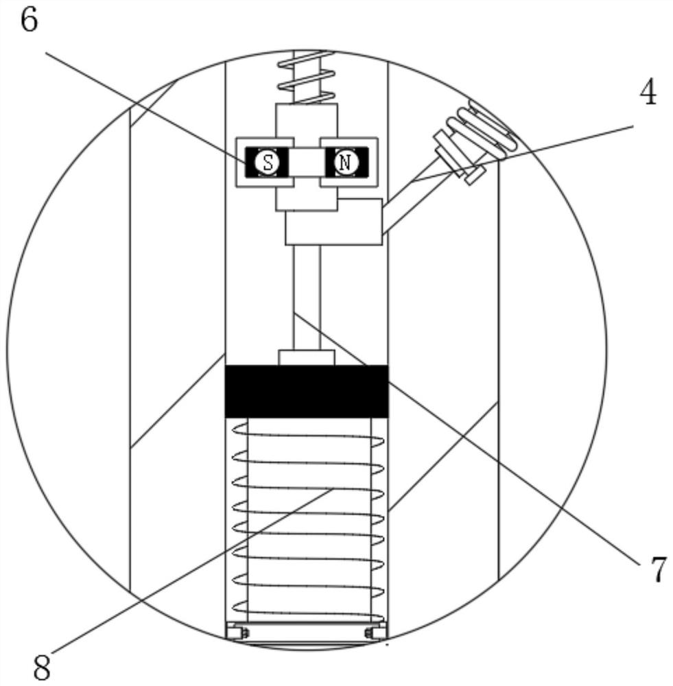
[0022] see Figure 1-4 , an automatic lubricating device for textile machine parts, comprising a lubricating box 1, the inside of the lubricating box 1 is movably connected with a conical block 2, the lower end of the conical block 2 is movably connected with a reset rod 3, and the outside of the conical block 2 The push-pull rod 4 is movably connected, and the reset rod 3 and the push-pull rod 4 are provided with two groups, and are evenly and symmetrically c...


PUM


Abstract

The invention relates to the technical field of textile equipment, and discloses a textile machine part automatic lubricating device which comprises a lubricating box. A conical blocking block is movably connected in the lubricating box, a reset rod is movably connected to the lower end of the conical blocking block, a permanent magnet is movably connected to the upper end of a sliding block, and an electromagnet is movably connected to the lower end of a sliding rod. An oil inlet head is movably connected to the lower end of the lubricating box, a glass oil inlet pipe is movably connected to the outer portion of the lubricating box, an air inlet pipe is movably connected to the upper end of the conical blocking block, a ventilation pipe is movably connected to the upper end of the air inlet pipe, and a compressed air bag is movably connected to the upper end of the ventilation pipe. The upper end of the compressed air bag is movably connected with a cover plate, the lower end of a pumping rod is movably connected with a movable clamping piece, and the outer portion of the lubricating box is movably connected with a rotating wheel. The device has the advantages that oil can be input automatically, oil leakage can be avoided when the device is not used, and meanwhile the oil input amount can be visually observed.

Description

technical field [0001] The invention relates to the technical field of textile equipment, in particular to an automatic lubricating device for textile machine parts. Background technique [0002] Natural fibers or chemical fibers are processed into various mechanical equipment required for textiles. In a broad sense, textile machinery also includes chemical machinery for the production of chemical fibers. Textile equipment is the production means and material basis of the textile industry. Its technical level, quality and manufacturing cost, It is directly related to the development of the textile industry, but in the existing small textile equipment, a small oil pot is still used to lubricate the equipment. The oil inlet of the oil pot is generally sealed, and sometimes it may cause the lubricant to overflow and flow It is too cumbersome to clean on the pot body, and the amount of oil dripped into the lubricating oil is generally based on the user's experience. The amount o...

Claims


Application Information

Patent Timeline
Patent Type & Authority Applications(China)
IPC IPC(8): F16N7/30F16N21/06
CPCF16N7/30F16N21/06
Inventor 严克光
Owner 成都滔洽未电子商务有限公司
Why Eureka
Try Eureka