Multi-input single-output distributed transformer and application circuit thereof
A distributed transformer and single output technology, applied in the field of transformers, can solve the problems of complex converter combination scheme and low manufacturing difficulty, and achieve the effect of low manufacturing difficulty, good adaptability and simplified circuit
- Summary
- Abstract
- Description
- Claims
- Application Information
AI Technical Summary
Problems solved by technology
Method used
Image

Examples
Embodiment 1
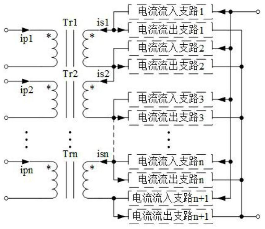
[0038] refer to figure 1 , a distributed transformer with multiple input and single output, including 2n ports on the primary side, 2 ports on the secondary side, n transformers, n+1 current inflow branches and n+1 current outflow branches, where n is greater than An integer of 1, one end of the primary side of the jth transformer and one end of the secondary side of the jth transformer have the same name. is the terminal with the same name, the 2j-1th port and the 2jth port of the primary side of the distributed transformer are respectively connected to one end and the other end of the jth primary side of the transformer, and the 2n-1th port of the primary side of the distributed transformer is connected to the The 2n ports are respectively connected to one end and the other end of the primary side of the nth transformer, and the first port of the secondary side of the distributed transformer is simultaneously connected to the current input ends of the first current inflow br...
Embodiment 2
[0053] refer to Figure 8 , an application circuit of a multi-input and single-output distributed transformer, comprising the distributed transformer described in Embodiment 1, n buffer branches, n switching devices and capacitors, the 2j-th primary side of the distributed transformer Port 1 is simultaneously connected to the positive end of the jth DC voltage source and one end of the jth buffer circuit, and the 2jth port on the primary side of the distributed transformer is simultaneously connected to the other end of the jth buffer circuit and one end of the jth switching device, The other end of the jth switching device is connected to the negative end of the jth DC voltage source, and the 2n-1th port of the primary side of the distributed transformer is simultaneously connected to the positive end of the nth DC voltage source and one end of the nth buffer circuit, The 2nth port of the primary side of the distributed transformer is connected to the other end of the nth buf...
Embodiment 3
[0068] refer to Figure 11 , an application circuit of a multi-input and single-output distributed transformer, comprising the distributed transformer described in Embodiment 1, n buffer branches, n switching devices and capacitors.
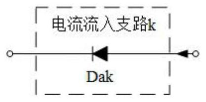
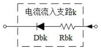
[0069] The first current inflow branch to the nth current inflow branch in the distributed transformer include diodes Da1 to Dan respectively, and the n+1th current inflow branch includes a series combination of diode Dcn+1 and inductor Lcn+1, the first The 1st current outflow branch includes a series combination of a diode Df1 and an inductor Lf1, and the second to n+1th current outflow branches include diodes Dd2 to Ddn+1 respectively.
[0070] The rest of embodiment 3 is the same as embodiment 2.
[0071] Still taking n=2 as an example, explain its working principle. refer to Figure 11 , assuming that the turn ratios of Tr1 and Tr2 are N1 and N2 respectively, the primary magnetizing inductances of Tr1 and Tr2 are Lmp1 and Lmp2 respectively...
PUM
 Abstract
Description
Claims
Application Information
 - R&D
- Intellectual Property
- Life Sciences
- Materials
- Tech Scout
- Unparalleled Data Quality
- Higher Quality Content
- 60% Fewer Hallucinations
Browse by: Latest US Patents, China's latest patents, Technical Efficacy Thesaurus, Application Domain, Technology Topic, Popular Technical Reports.
© 2025 PatSnap. All rights reserved.Legal|Privacy policy|Modern Slavery Act Transparency Statement|Sitemap|About US| Contact US: help@patsnap.com