Device and method for coordinating power supply systems of two low-voltage transformer areas

A low-voltage station area and power supply system technology, applied in the direction of circuit devices, power network operating system integration, system integration technology, etc., can solve problems such as power grid failures

Inactive Publication Date: 2021-06-04
国网浙江省电力有限公司宁波市北仑区供电公司 +1
0 Cites 0 Cited by

AI-Extracted Technical Summary

Problems solved by technology

However, in the daily operation of the low-voltage distribution netw...

Abstract

The invention provides a two-low-voltage transformer area power supply system coordination device. The device comprises a main control module, a data acquisition module and a power support module, detects power distribution data in real time, and controls the power support module to provide short-time power support for a non-fault low-voltage transformer area through the main control module, so the power supply reliability of the power supply system is improved. The invention also provides a two-low-voltage transformer area power supply system coordination method. The method comprises the steps of dividing the two low-voltage transformer areas into a first transformer area and a second transformer area, collecting power distribution data of the two low-voltage transformer areas, comparing the power distribution data of the two low-voltage transformer areas, screening out a fault transformer area, and discharging the energy storage system for short-time operation of a conventional load in the fault transformer area, so the electricity demand of electric appliances in the low-voltage transformer area in the maintenance stage is met.

Application Domain

Power network operation systems integrationContigency dealing ac circuit arrangements +4

Technology Topic

Data acquisition moduleTransformer +5

Image

  • Device and method for coordinating power supply systems of two low-voltage transformer areas
  • Device and method for coordinating power supply systems of two low-voltage transformer areas

Examples

  • Experimental program(1)

Example Embodiment

[0034] Example:
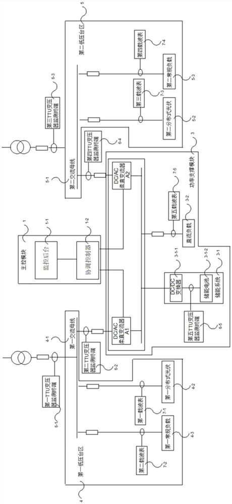
[0035] A coordinating device for the power supply system of two low-voltage stations, the two low-voltage stations are divided into a first low-voltage station 4 and a second low-voltage station 5, the first low-voltage station 4 includes a 400V first AC bus 4-1, a 10kWp second A distributed photovoltaic 4-2 and a first conventional load 4-3, the second low-voltage platform area 5 includes a 400V second AC bus 5-1, a 10kWp second distributed photovoltaic 5-2 and a second conventional load 5-3, The conventional load is specifically an AC charging pile; the coordinating device of the power supply system of the two low-voltage stations includes a main control module 1, a data acquisition module 2 and a power support module 3, and the main control module 1 includes a coordination controller 1-2 and The monitoring background 1-1, the coordinating controller 1-2 and the monitoring background 1-1 are connected through optical fiber communication, and the monitoring background 1-1 is used to receive and organize the power distribution data collected by the data acquisition module 2, and is used by the coordinating controller 1-2 To issue a control command to the power support module 3; the data acquisition module 2 is connected to the main control module 1 in communication, and the data acquisition module 2 is used to collect power distribution data and transmit the power distribution data to the main control module 1 for processing and Save; the power support module 3 is connected to the main control module 1 and used to provide support power after receiving a control command from the main control module 1 .
[0036] The power support module 3 includes a 150kW DC/AC flexible DC converter A1, a 150kW DC/AC flexible DC converter A2, a 150kW energy storage system 3-1 and a DC load 3-2, and the DC load is specifically a DC charging pile; the AC terminals of the DC/AC flexible DC converter A1 and the DC/AC flexible DC converter A2 are respectively connected to the first AC bus 4-1 and the second AC bus 5-1, and the DC The DC terminal of the /AC flexible DC converter A1 and the DC terminal of the DC/AC flexible DC converter A2 are connected to each other to construct a power transmission device 3-3; the energy storage system 3-1 includes a DC/DC converter 3- 1-1 and an energy storage battery 3-1-2, wherein the energy storage battery 3-1-2 is connected to a power transmission device 3-3 through a DC/DC converter 3-1-1; the DC load 3-2 Connected to the power transmission device 3-3.
[0037] The data acquisition module 2 includes several TTU distribution transformer monitoring terminals 6 and several carrier meters 7, and the first TTU power distribution for collecting transformer low-voltage side power distribution data is connected between the first AC bus 4-1 and the transformer. The transformer monitoring terminal 6-1 is connected between the first AC bus 4-1 and the power support module 3. The second TTU distribution transformer monitoring terminal 6- for collecting the AC terminal power distribution data of the DC/AC flexible DC converter A1 2. The third TTU distribution transformer monitoring terminal 6-3 is connected between the second AC bus 5-1 and the transformer for collecting power distribution data on the low-voltage side of the transformer, and between the second AC bus 5-1 and the power support module 3 Connected with the fourth TTU distribution transformer monitoring terminal 6-4 for collecting the AC terminal power distribution data of the DC/AC flexible DC converter A2, the energy storage battery 3-1-2 and the DC/DC converter 3-1-1 The fifth TTU distribution transformer monitoring terminal 6-5 for collecting the output distribution data of the energy storage battery 3-1-2 is connected between them; between the first AC bus 4-1 and the first distributed photovoltaic 4-2 A first carrier meter 7-1 is connected to collect power distribution data at the output end of the first distributed photovoltaic 4-2, and a first carrier meter 7-1 is connected between the first AC bus 4-1 and the first conventional load 4-3 for collecting the first conventional load. The second carrier meter 7-2 of the power distribution data of the load 4-3, the second AC bus 5-1 and the second distributed photovoltaic 5-2 are connected to the second distributed photovoltaic 5-2 for collecting the output power distribution of the second distributed photovoltaic 5-2 A third carrier meter 7-3 for data, a fourth carrier meter 7-4 for collecting power distribution data of the second conventional load 5-3 is connected between the second AC bus 5-1 and the second conventional load 5-3, A fifth carrier meter 7-5 for collecting power distribution data of the DC load 3-2 is connected between the DC load 3-2 and the power transfer device.
[0038] The coordination controller 1-2 includes a coordination control host and a coordination control sub-machine, the coordination control host is arranged in the first low-voltage station area 4, and the coordination control sub-machine is arranged in the second low-voltage station area 5; Both the coordinating controller 1-2 and the monitoring background 1-1 are equipped with a switchboard and a comprehensive communication device PCS-9799M.
[0039] A method for coordinating the power supply systems of two low-voltage stations, which is applicable to the above-mentioned coordinating device for the power supply systems of the two low-voltage stations, comprising the following steps:
[0040] Step 1: According to the historical station area load data recorded by the monitoring background 1-1, the two pressure station areas are divided into a first low-voltage station area 4 and a second low-voltage station area 5, and the first low-voltage station area 4 is connected to the coordination control host, so The second low-voltage platform area 5 is connected to the coordination control sub-machine;
[0041] Step 2: Collect the first power distribution data of the transformers in the first low-voltage station area 4 and the second power distribution data of the transformers in the second low-voltage station area 5 every preset period;
[0042] Step 3: The coordinating controller 1-2 analyzes the first power distribution data and the second power distribution data, and screens out the faulty station area. If the first low-voltage station area 4 or the second low-voltage station area 5 fails, the power support module The energy storage system is discharged for short-term operation of normal loads in the faulty station area.
[0043] In step 1, the coordinated control host computer also collects the position of the molded case circuit breaker B1 set in the first low-voltage station area 4, the voltage on the low-voltage side of the substation and the current on the low-voltage side of the substation, and the coordinating control host sends out control commands to Control the opening and closing of the molded case circuit breaker B1; the coordinated control sub-machine also collects the position of the molded case circuit breaker B2 connected to the low-voltage side of the second low-voltage platform area 5, the voltage of the low-voltage side of the transformer and the current of the low-voltage side of the transformer. The coordinated control sub-machine controls the opening and closing of the molded case circuit breaker B2 by issuing a control command; the coordinated control host receives the information collected by the control sub-machine through optical fiber communication and sends a control command, and the coordinated control sub-machine also receives the coordinated control The control command of the host computer is used to control the tripping of the output contact of the molded case circuit breaker B2.
[0044] In step 2, the first power distribution data includes the transformer low-voltage side current in the first low-voltage station area 4 , and the second power distribution data includes the transformer low-voltage side current in the second station area 5 .
[0045] In step 3, the coordinating controller 1-2 compares the first power distribution data and the second power distribution data with the historical data, and if there is a substantial increase, it is judged that the station area with the large increase phenomenon is a faulty station area.
[0046] When a fault occurs in the first low-voltage station area 4 or the second low-voltage station area 5 screened out in step 3, the coordinating controller 1-2 issues a control command to control the output contacts of the molded case circuit breaker B1 or the molded case circuit breaker B2 to trip.
[0047] Discharging 3-1 of the energy storage system in Step 3 includes the following steps:
[0048] 4.1 The control coordinator 1-2 issues control commands;
[0049] 4.2 The energy storage battery in the energy storage system 3-1 discharges 3-1-2 and performs boost processing through the DC/DC converter 3-1-1;
[0050] 4.3 After the step-up treatment, the electric energy is transmitted to the two low-voltage areas to maintain the short-term operation of the loads in the two areas.

PUM

no PUM

Description & Claims & Application Information

We can also present the details of the Description, Claims and Application information to help users get a comprehensive understanding of the technical details of the patent, such as background art, summary of invention, brief description of drawings, description of embodiments, and other original content. On the other hand, users can also determine the specific scope of protection of the technology through the list of claims; as well as understand the changes in the life cycle of the technology with the presentation of the patent timeline. Login to view more.
Why Eureka
Try Eureka