
House building carrying frame with an anti-falling function and using method

A technology for carrying racks and anti-falling, applied in safety belts, life-saving equipment, etc., can solve problems such as tight project progress, slow improvement of work efficiency, and time-consuming

Active Publication Date: 2021-06-08
ZHEJIANG ZHONGFU CONSTR GRP
View PDF7 Cites 0 Cited by
  • Summary
  • Abstract
  • Description
  • Claims
  • Application Information

AI Technical Summary

Problems solved by technology

[0003] The Chinese patent with the patent number CN201820026913.4 in the prior art discloses a fall-proof building construction support, including a bottom plate, both sides of the bottom of the bottom plate are fixedly connected with supporting columns, and the middle part of the bottom of the bottom plate is fixedly connected There is a ladder, the top of the bottom plate is fixedly connected with a base, both sides of the top of the bottom plate are fixedly connected with baffle plates, both sides of the top of the base are fixedly connected with protective plates, and the fronts of the two protective plates are A handle is fixedly connected, and a connecting block is fixedly connected to the tops of the two protective plates; the anti-fall housing construction bracket is threadedly connected to the first lock block and the second lock block by manually adjusting the threaded rod, so that the safety door is closed , so as to achieve the purpose of high safety and fall prevention. However, in the specific use process, due to the heavy construction site and the tense progress of the project, workers need to manually turn the threaded rod every time the house construction carrier is used, which will take a lot of time , which is not conducive to meeting the needs of actual work, and the work efficiency is slowly improved

Method used


Image

  • House building carrying frame with an anti-falling function and using method
  • House building carrying frame with an anti-falling function and using method
  • House building carrying frame with an anti-falling function and using method

Examples


Embodiment 1

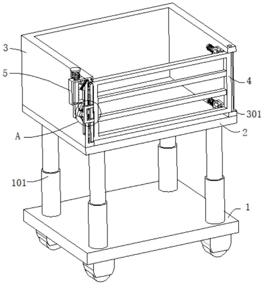
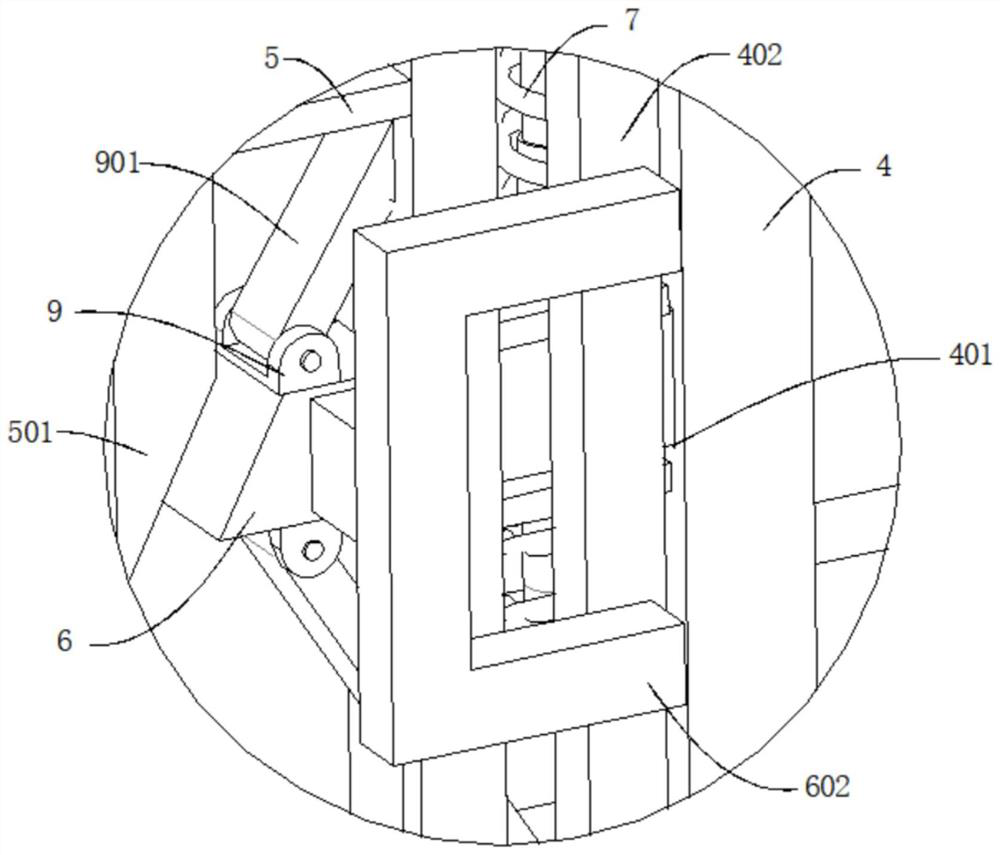
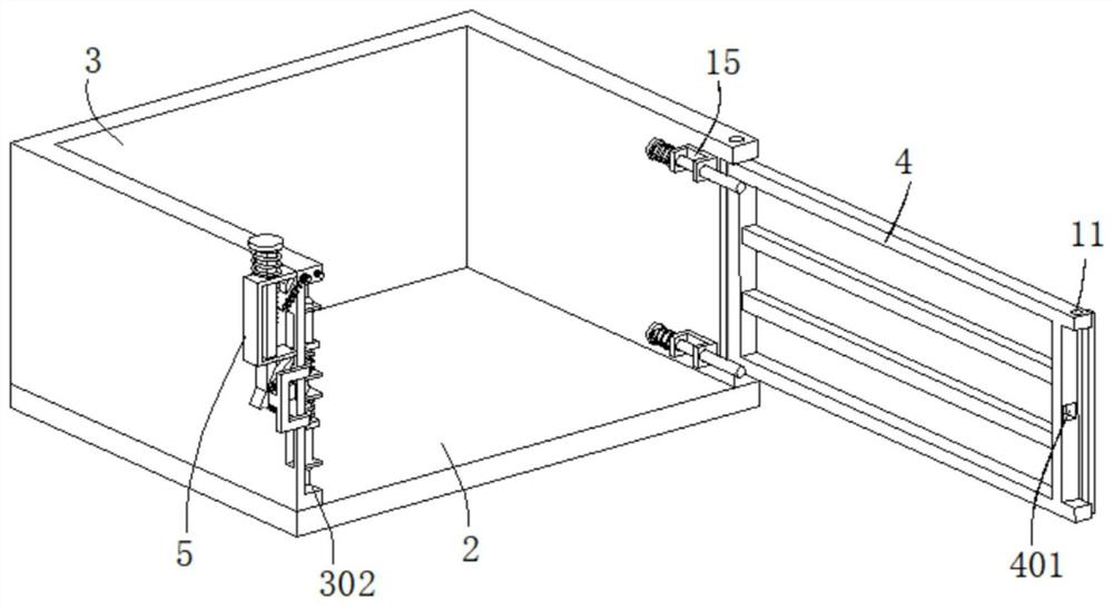
[0037] refer to Figure 1-6 , a house construction frame with fall prevention, comprising a bottom plate 1, the top of the bottom plate 1 is connected with a support column 101, the end of the support column 101 away from the bottom plate 1 is connected with a workbench 2, and the top outer wall of the workbench 2 is connected with a U-shaped Protective plate 3, the outer wall of U-shaped protective plate 3 is dug with a first groove 301, the inner wall of the first groove 301 is connected with a rotating shaft, the outer wall of the rotating shaft is connected with a door panel 4, and the end of the U-shaped protective plate 3 away from the first groove 301 is dug with a The second groove 302, the door panel 4 is movably connected in the second groove 302, the U-shaped protective plate 3 outer wall is connected with a U-shaped frame 5, the U-shaped frame 5 is slidingly connected with a moving bar 501, and the top of the moving bar 501 is connected with a Press the plate 502, ...

Embodiment 2

[0044] refer to Figure 1-6 , a kind of housing construction carrying rack with anti-falling, basically the same as embodiment 1, furthermore, the limit mechanism includes a positioning plate 12, and the positioning plate 12 is fixedly connected to the outer wall of the U-shaped protective plate 3, and the outer wall of the positioning plate 12 The hinge is connected to the limiting plate 121, and the limiting plate 121 is movable against the positioning plate 12, and the outer wall of the limiting plate 121 is connected with a second elastic element 122, and the end of the second elastic element 122 away from the limiting plate 121 is connected to the U-shaped protective plate 3 Connected, the outer wall of the moving rod 501 is connected with the limit tooth 5011, and the limit plate 121 is movable against the limit tooth 5011.

[0045] The outer wall of the limiting plate 121 is connected with a third elastic element 13 through a fixed shaft, and the end of the third elasti...

Embodiment 3

[0049] refer to Figure 1-7 , a housing construction carrying frame with anti-falling, which is basically the same as that of Embodiment 2, furthermore, a U-shaped piece 15 is connected to the inner wall of the U-shaped protective plate 3, and the U-shaped piece 15 is slidably connected to a limit rod 151 to limit The outer wall of the position rod 151 is connected with a push plate 152, and the outer wall of the limit rod 151 is sleeved with a fourth elastic element 153. One end of 152 is moved against the door panel 4; when the lock of the door panel 4 is released, the door panel 4 no longer acts on the limit rod 151, and the fourth elastic element 153 resumes deformation, and pulls the push plate 152 to move, so that the push plate 152 drives The limit lever 151 exerts force on the door panel 4, so that the door panel 4 is opened, and after the door panel 4 rotates 90 degrees with the rotating shaft as the center of a circle, the limit lever 151 is placed on the side of the...


PUM


Abstract

The invention discloses a house building carrying frame with an anti-falling function and a using method, and belongs to the technical field of house building. The house building carrying frame with the anti-falling function comprises a bottom plate, a supporting column is connected to the top of the bottom plate, a workbench is connected to the end, away from the bottom plate, of the supporting column, a U-shaped protection plate is connected to the outer wall of the top of the workbench, a first groove is formed in the outer wall of the U-shaped protection plate, a rotating shaft is connected to the inner wall of the first groove, a door plate is connected to the outer wall of the rotating shaft, a second groove is formed in the end, away from the first groove, of the U-shaped protection plate, the door plate is movably connected into the second groove, a U-shaped frame is connected to the outer wall of the U-shaped protection plate, a moving rod is slidably connected into the U-shaped frame, a pressing plate is connected to the top of the moving rod, and the outer wall of the moving rod is sleeved with a first elastic element. The door plate can be quickly closed, the operation time is saved, the working efficiency is improved, multiple locking of the door plate is achieved, the safety protection performance is improved, and the actual working requirement is met.

Description

technical field [0001] The invention relates to the technical field of house construction, in particular to a house construction carrying frame with anti-fall and a use method. Background technique [0002] Housing construction refers to the housing that people carry out production, living and living, such as industrial buildings, civil buildings and agricultural buildings. Lines, pipelines, equipment installation projects and indoor and outdoor decoration projects, house construction often need to work on high construction frames, people will use various measures to prevent falling, and the anti-falling house construction carrying frame is one of the common ones . [0003] The Chinese patent with the patent number CN201820026913.4 in the prior art discloses a fall-proof building construction support, including a bottom plate, both sides of the bottom of the bottom plate are fixedly connected with supporting columns, and the middle part of the bottom of the bottom plate is ...

Claims


Application Information

Patent Timeline
IPC IPC(8): A62B35/00
CPCA62B35/00
Inventor 劳远明
Owner ZHEJIANG ZHONGFU CONSTR GRP
Learn More