A house construction carrying frame with anti-fall and using method
A carrying frame and anti-falling technology, applied in safety belts, life-saving equipment, etc., can solve the problems of unfavorable meeting the needs of actual work, slow improvement of work efficiency, time-consuming and other problems, so as to improve safety protection and save operation time , Strengthen the effect of multiple locks
- Summary
- Abstract
- Description
- Claims
- Application Information
AI Technical Summary
Problems solved by technology
Method used
Image
Examples
Embodiment 1
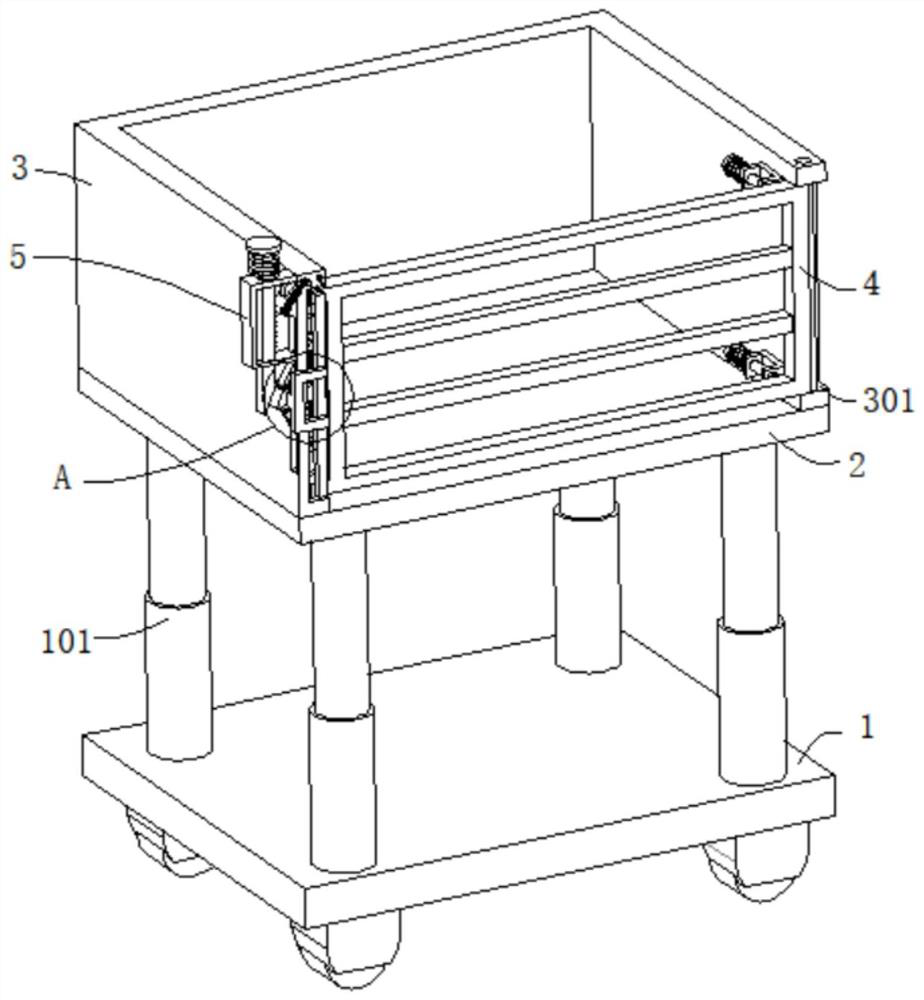
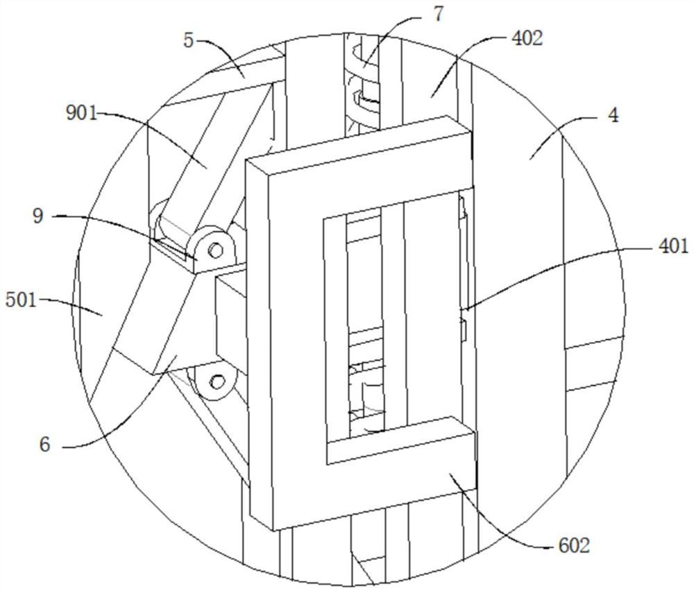
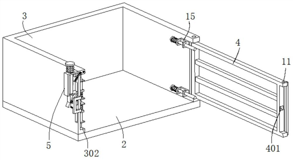
[0036] refer to Figure 1-6 , a house construction frame with fall prevention, comprising a bottom plate 1, the top of the bottom plate 1 is connected with a support column 101, the end of the support column 101 away from the bottom plate 1 is connected with a workbench 2, and the top outer wall of the workbench 2 is connected with a U-shaped Protective plate 3, the outer wall of U-shaped protective plate 3 is dug with a first groove 301, the inner wall of the first groove 301 is connected with a rotating shaft, the outer wall of the rotating shaft is connected with a door panel 4, and the end of the U-shaped protective plate 3 away from the first groove 301 is dug with a The second groove 302, the door panel 4 is movably connected in the second groove 302, the U-shaped protective plate 3 outer wall is connected with a U-shaped frame 5, the U-shaped frame 5 is slidingly connected with a moving bar 501, and the top of the moving bar 501 is connected with a Press the plate 502, ...
Embodiment 2
[0042] refer to Figure 1-6 , a kind of housing construction carrying rack with anti-falling, basically the same as embodiment 1, furthermore, the limit mechanism includes a positioning plate 12, and the positioning plate 12 is fixedly connected to the outer wall of the U-shaped protective plate 3, and the outer wall of the positioning plate 12 The hinge is connected to the limiting plate 121, and the limiting plate 121 is movable against the positioning plate 12, and the outer wall of the limiting plate 121 is connected with a second elastic element 122, and the end of the second elastic element 122 away from the limiting plate 121 is connected to the U-shaped protective plate 3 Connected, the outer wall of the moving rod 501 is connected with the limit tooth 5011, and the limit plate 121 is movable against the limit tooth 5011.
[0043] The outer wall of the limiting plate 121 is connected with a third elastic element 13 through a fixed shaft, and the end of the third elasti...
Embodiment 3
[0047] refer to Figure 1-7 , a housing construction carrying frame with anti-falling, which is basically the same as that of Embodiment 2, furthermore, a U-shaped piece 15 is connected to the inner wall of the U-shaped protective plate 3, and the U-shaped piece 15 is slidably connected to a limit rod 151 to limit The outer wall of the position rod 151 is connected with a push plate 152, and the outer wall of the limit rod 151 is sleeved with a fourth elastic element 153. One end of 152 is moved against the door panel 4; when the lock of the door panel 4 is released, the door panel 4 no longer acts on the limit rod 151, and the fourth elastic element 153 resumes deformation, and pulls the push plate 152 to move, so that the push plate 152 drives The limit lever 151 exerts force on the door panel 4, so that the door panel 4 is opened, and after the door panel 4 rotates 90 degrees with the rotating shaft as the center of a circle, the limit lever 151 is placed on the side of the...
PUM
 Abstract
Description
Claims
Application Information
 - R&D
- Intellectual Property
- Life Sciences
- Materials
- Tech Scout
- Unparalleled Data Quality
- Higher Quality Content
- 60% Fewer Hallucinations
Browse by: Latest US Patents, China's latest patents, Technical Efficacy Thesaurus, Application Domain, Technology Topic, Popular Technical Reports.
© 2025 PatSnap. All rights reserved.Legal|Privacy policy|Modern Slavery Act Transparency Statement|Sitemap|About US| Contact US: help@patsnap.com


