
Automatic dispensing device

An automatic dispensing and dispensing technology, which is applied in the direction of spraying device, device for coating liquid on the surface, coating, etc., can solve the problem that precise dispensing cannot be realized

Pending Publication Date: 2021-06-08
SHENZHEN TENSUN IND EQUIP
View PDF0 Cites 3 Cited by
  • Summary
  • Abstract
  • Description
  • Claims
  • Application Information

AI Technical Summary

Problems solved by technology

However, due to the linear motion limitation of the three-axis platform dispensing method of the existing dispensing machine, it is suitable for the dispensing before the assembly of the full screen, special-shaped screen, water drop screen or waterfall screen of the mobile phone with the middle frame of the mobile phone, and for the display module. Precision dispensing cannot be achieved in the fields of side edge dispensing, coating sealing, TP, LCM gap filling and other dispensing occasions for special shaped products

Method used


Image

  • Automatic dispensing device
  • Automatic dispensing device
  • Automatic dispensing device

Examples


Embodiment Construction

[0032] Unless otherwise defined, all technical and scientific terms used herein have the same meaning as commonly understood by those skilled in the technical field of the application; the terms used herein in the description of the application are only for the purpose of describing specific embodiments , is not intended to limit the present application; the terms "comprising" and "having" and any variations thereof in the description and claims of the present application and the description of the above drawings are intended to cover non-exclusive inclusion. The terms "first", "second" and the like in the description and claims of the present application or the above drawings are used to distinguish different objects, rather than to describe a specific order.

[0033] Herein, those skilled in the art need to understand that the terms indicating orientation or positional relationship herein are based on the orientation or positional relationship shown in the drawings, and are o...


PUM


Abstract

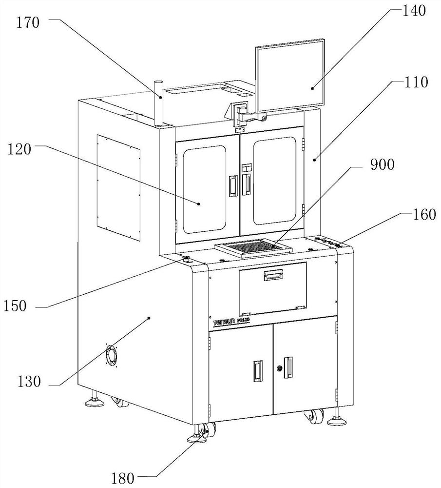
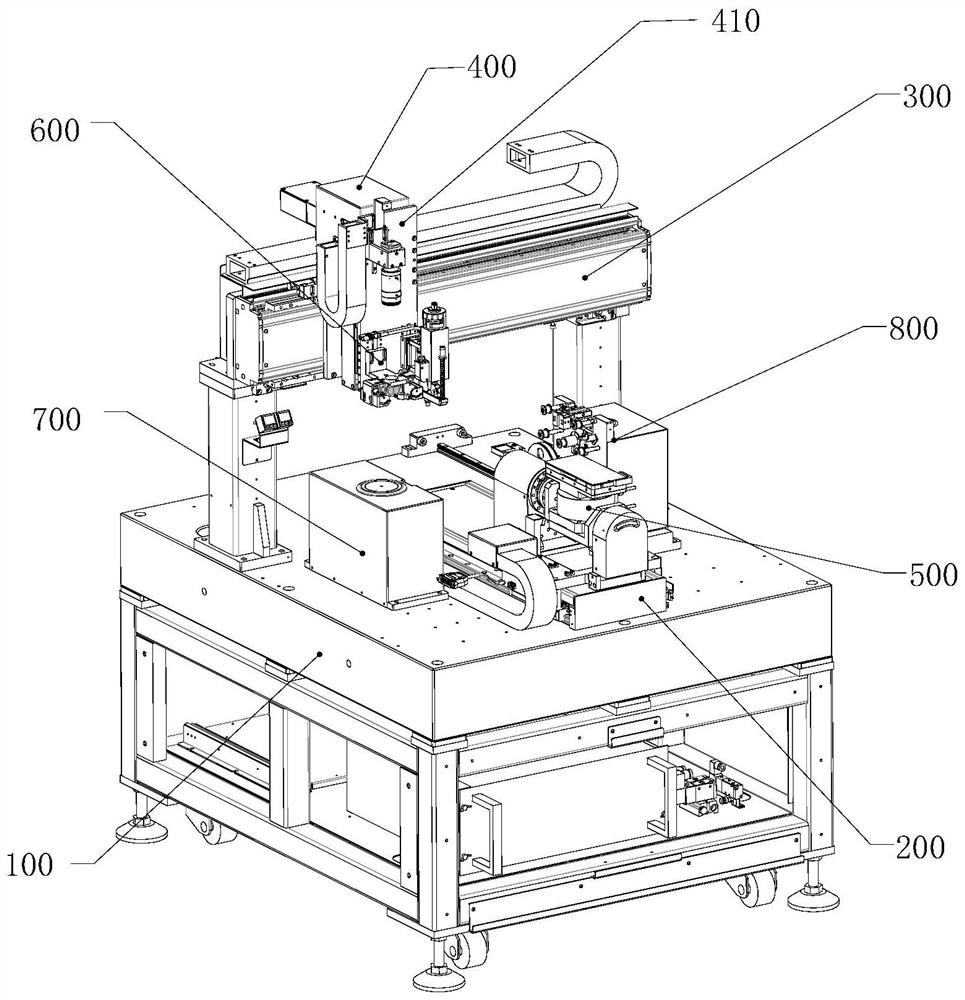
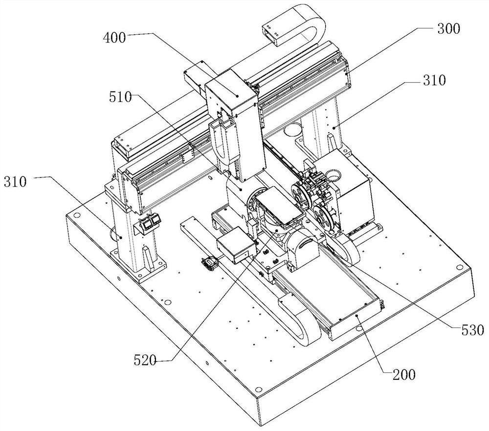
The embodiment of the invention relates to an automatic dispensing device. The automatic dispensing device comprises a rack, an X-axis module, a Y-axis module, a Z-axis module, a dispensing mechanism and a workpiece rotating mechanism, wherein the X-axis module and the Y-axis module are both fixedly arranged on the rack, the Z-axis module is slidably arranged on the X-axis module, the dispensing mechanism is slidably arranged on the Z-axis module through a connecting part, and the workpiece rotating mechanism is slidably arranged on the Y-axis module; and the workpiece rotating mechanism comprises a first rotating assembly, a second rotating assembly and a locating jig, the first rotating assembly is slidably arranged on the Y-axis module, the second rotating assembly is arranged on the first rotating assembly, and the locating jig is arranged on the second rotating assembly. The locating jig can realize multi-angle movement through cooperation of the Y-axis module, the first rotating assembly and the second rotating assembly, the position and distance of the dispensing mechanism relative to a workpiece to be subjected to dispensing can be adjusted through the X-axis module and the Z-axis module, and therefore full-automatic dispensing on a complex special-shaped curved surface can be realized.

Description

technical field [0001] The present application relates to the technical field of glue dispensing, and more specifically, to an automatic glue dispensing device. Background technique [0002] With the development of science and technology, the application of dispensing has been very extensive. As a kind of automatic mechanical equipment, dispensing equipment is widely used in dispensing, coating, pouring, sealing, bonding and other occasions in the production process of products. However, with the continuous innovation and development of science and technology, more and more electronic products tend to be highly integrated, so that high-precision dispensing technology with complex curved surfaces is required in the packaging technology of electronic products. [0003] At present, the dispensing machines on the market generally use the three-axis platform dispensing method, and realize the non-contact dispensing effect through the jet valve. However, due to the linear motion ...

Claims


Application Information

Patent Timeline
Patent Type & Authority Applications(China)
IPC IPC(8): B05C5/02B05C13/02B05C11/10B05B15/55
CPCB05C5/0208B05C11/101B05C11/1018B05C11/1021B05C13/02B05B15/55
Inventor 李复春卢国艺张圆圆胡涛黎平江岱平王付详
Owner SHENZHEN TENSUN IND EQUIP
Learn More