Optical fiber automatic tube penetrating machine

An automatic pipe threading machine and optical fiber technology, which is applied in fiber mechanical structure, optical fiber/cable installation, optics, etc., can solve the problems of high labor intensity, low efficiency, and easy fiber core breakage, so as to reduce labor intensity and improve pipe penetration. The effect of efficiency

Pending Publication Date: 2020-09-22
东莞鸿辉光联通讯技术有限公司
View PDF0 Cites 3 Cited by
  • Summary
  • Abstract
  • Description
  • Claims
  • Application Information

AI Technical Summary

Problems solved by technology

In the prior art, the fiber core is generally threaded into a glass tube manually, which is inefficient, the fiber core is easily broken, and the labor intensity is high.

Method used


Image

  • Optical fiber automatic tube penetrating machine
  • Optical fiber automatic tube penetrating machine
  • Optical fiber automatic tube penetrating machine

Examples


Embodiment Construction

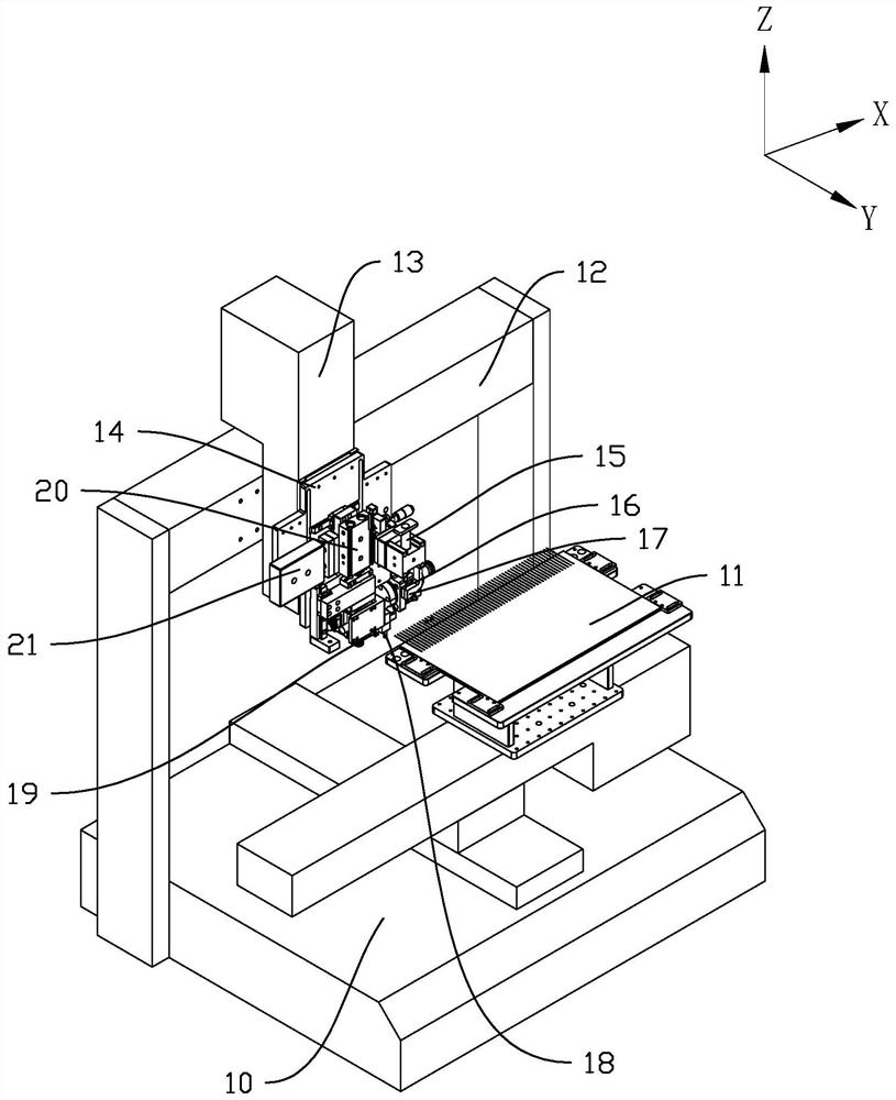
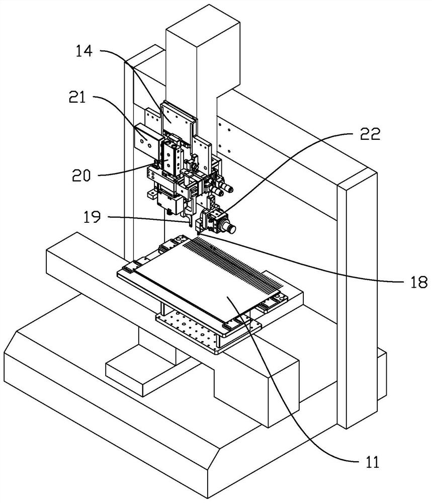
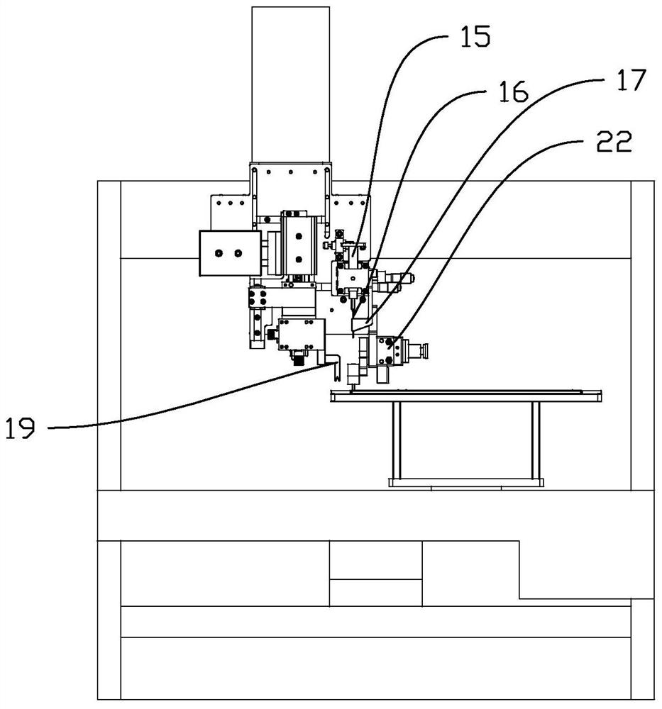
[0022] This part will describe the specific embodiment of the present invention in detail, and the preferred embodiment of the present invention is shown in the accompanying drawings. Each technical feature and overall technical solution of the invention, but it should not be understood as a limitation on the protection scope of the present invention.

[0023] In the description of the present invention, it should be understood that the orientation descriptions, such as up, down, front, back, left, right, etc. indicated orientations or positional relationships are based on the orientations or positional relationships shown in the drawings, and are only In order to facilitate the description of the present invention and simplify the description, it does not indicate or imply that the device or element referred to must have a specific orientation, be constructed and operated in a specific orientation, and thus should not be construed as limiting the present invention.

[0024] I...


PUM


Abstract

The invention discloses an optical fiber automatic tube penetrating machine which comprises a workbench, a fiber arranging plate and a mechanical arm. The fiber arranging plate is provided with a plurality of fixing grooves used for containing optical fibers, and the fiber arranging plate is arranged on the workbench and can reciprocate in the X-axis direction and the Y-axis direction; the mechanical arm is arranged above the workbench; the mechanical arm is provided with a glue dripping device and a rotatable tube clamp, after the tube clamp rotates, the hole of the glass pipe can receive glue of the glue dripping device, the mechanical arm drives the tube clamp to move along the Z axis to align the hole of the glass tube with the optical fiber, and the fiber arranging plate moves forwards in the Y-axis direction to enable a fiber core of the optical fiber to penetrate into the hole of the glass pipe. Automatic glue dripping of the glass tube is achieved, automatic tube penetrating ofthe fiber core of the optical fiber is also achieved, the tube penetrating efficiency of the optical fiber is improved, and the labor intensity of operators is reduced.

Description

technical field [0001] The invention relates to a device in the field of manufacturing research of optical fiber passive components, in particular to an automatic optical fiber tube threading machine. Background technique [0002] Optical fiber is an abbreviation for fiber waveguide or optical fiber that transmits light. Its typical structure is a multi-layer coaxial cylinder with core, cladding and coating from the inside to the outside. The core part is the core and the cladding, in which the core is made of highly transparent material and is the main transmission channel of light waves; the refractive index of the cladding is slightly smaller than that of the core, making the light transmission performance relatively stable. The thickness of the core, the refractive index of the core material and the cladding material have a decisive influence on the characteristics of the fiber. The coating layer includes primary coating, buffer layer and secondary coating, which prote...

Claims


Application Information

Patent Timeline
Patent Type & Authority Applications(China)
IPC IPC(8): G02B6/44G02B6/50
CPCG02B6/508G02B6/50
Inventor 范卫星
Owner 东莞鸿辉光联通讯技术有限公司
Why Eureka
Try Eureka