High-voltage wiring harness system for new energy automobile

A technology for new energy vehicles and high-voltage wiring harnesses, applied in vehicle parts, electrical components, circuits or fluid pipelines, etc., can solve problems such as trouble

Active Publication Date: 2021-06-08
HEMEI (ZHEJIANG) AUTOMOBILE CO LTD
View PDF5 Cites 2 Cited by
  • Summary
  • Abstract
  • Description
  • Claims
  • Application Information

AI Technical Summary

Problems solved by technology

[0003] The invention provides a high-voltage wire harness system for new energy vehicles, which has the beneficial effect of easy installation, and solves the need f...

Method used


Image

  • High-voltage wiring harness system for new energy automobile
  • High-voltage wiring harness system for new energy automobile
  • High-voltage wiring harness system for new energy automobile

Examples


Embodiment 1

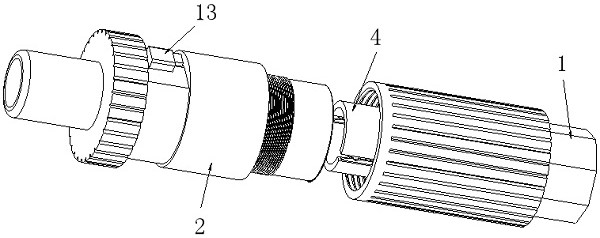
[0025] see Figure 1-3 , a high-voltage wire harness system for new energy vehicles, including a first joint 1 and a second joint 2, both of which are hollow structures, and one end of the first joint 1 is provided with a first fixing groove 3, And the first fixing groove 3 is provided with a wire harness fixing seat 4, and the wire harness fixing seat 4 is elastically connected with the first fixing groove 3 through an elastic connector 5, and the outside of the wire harness fixing seat 4 is provided with a first knife rod 6, and a second joint One end of 2 is provided with a second fixing groove 7, and a second knife rod 8 is arranged in the second fixing groove 7. The wire harness holder 4 is cylindrical, and one end of the wire harness holder 4 is provided with a plurality of notches 401 , and two splints 402 are arranged symmetrically inside the notch 401 , and the outer side of the splint 402 is provided with an arc-shaped limiting groove.

[0026] The push-in connector...

Embodiment 2

[0029] Please further combine on the basis of Example 1 Figure 4 , the difference between embodiment 2 and embodiment 1 is that: the wire harness holder 4 is cylindrical, and one end of the wire harness holder 4 is provided with several notches 401, and two splints 402 are symmetrically provided in the notches 401, and The outer side of the splint 402 is provided with several conical protrusions. In Embodiment 1, only one arc-shaped limiting groove is provided on the outer side of the splint 402, which makes the fixing position of the wire harness fixed when the wire harness is fixed. Yes, in this technical solution, several tapered protrusions are arranged on the splint 402, and the wire harness can be clamped between any two tapered protrusions when it is fixed, which is more flexible.

Embodiment 3

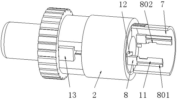
[0031] Please further combine on the basis of Example 1 figure 2 and image 3, this embodiment is a further improvement on Embodiment 1, the bottom end of the first knife bar 6 is fixedly connected with the first joint 1, and the position and number of the first knife bar 6 correspond to the notch 401 one by one, the first knife bar The front end of the rod 6 is provided with a first cutter 9 , and one side of the first cutter rod 6 is provided with a limiting rod 10 . The limiting rod 10 is L-shaped, and one end of the limiting rod 10 is fixedly connected with the first knife rod 6 , and the other end of the limiting rod 10 is provided with a slot. One end of the second knife bar 8 is fixedly connected with the second joint 2, and the other end of the second knife bar 8 is provided with a second cutting knife 11, and the back of the second knife bar 8 is provided with a limiting rib 801, and the second cutting knife The tail of the knife 11 is provided with a limit groove ...


PUM


Abstract

The invention relates to the technical field of automobile wire harnesses, and discloses a high-voltage wire harness system for a new energy automobile, the high-voltage wire harness system comprises a first connector and a second connector, the first connector and the second connector are both of hollow structures, one end of the first connector is provided with a first fixing groove, and a wire harness fixing seat is arranged in the first fixing groove; the wire harness fixing seat is elastically connected with the first fixing groove through an elastic connecting piece, a first cutter bar is arranged on the outer side of the wire harness fixing seat, a second fixing groove is formed in one end of the second connector, and a second cutter bar is arranged in the second fixing groove. According to the technical scheme, the first cutter bar with the first cutter is arranged in the first connector, and the second cutter bar with the second cutter is arranged in the second connector, so that when the first connector is inserted into the second connector, an insulating layer of a conductor fixed on the guide fixing seat can be cut off through the first cutter and the second cutter; therefore, the purpose of avoiding manual wire stripping is achieved.

Description

technical field [0001] The invention relates to the technical field of automotive wiring harnesses, in particular to a high-voltage wiring harness system for new energy vehicles. Background technique [0002] The automobile wiring harness is the network main body of the automobile circuit, which connects the electrical and electronic components of the automobile and enables them to function. Without the wiring harness, there is no automobile circuit. The wire harness refers to the contact piece terminal punched from copper and the wire and cable crimped, and the outside is molded with an insulator or a metal shell, etc., and is bundled with a wire harness to form a connected circuit assembly. In addition to using terminal blocks, many wiring harnesses are also connected with quick-plug connectors. When installing the existing automotive wiring harness quick-plug connectors, it is generally necessary to peel off the insulation layer of the wiring harness first, and then conne...

Claims


Application Information

Patent Timeline
IPC IPC(8): B60R16/02H01R4/2433H01R4/26
CPCB60R16/02B60R16/0215H01R4/2433H01R4/26
Inventor 陈阔崔臻孔维强陶广华朱福雄杜克虎王远东沈玉平蒋剑耿强
Owner HEMEI (ZHEJIANG) AUTOMOBILE CO LTD
Why Eureka
Try Eureka