
Anti-collision device for traffic engineering

An anti-collision device and traffic engineering technology, which is applied in the field of traffic engineering, can solve problems such as simple structure and poor anti-collision effect

Active Publication Date: 2021-06-08
石凯
View PDF14 Cites 0 Cited by
  • Summary
  • Abstract
  • Description
  • Claims
  • Application Information

AI Technical Summary

Problems solved by technology

There are anti-collision devices on both sides of the road section where collisions are prone to occur, but the traditional anti-collision devices use simple springs for anti-collision work, the structure is simple, and the anti-collision effect is not good

Method used


Image

  • Anti-collision device for traffic engineering
  • Anti-collision device for traffic engineering
  • Anti-collision device for traffic engineering

Examples


Embodiment 1

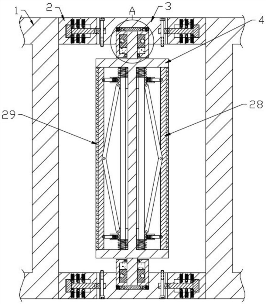
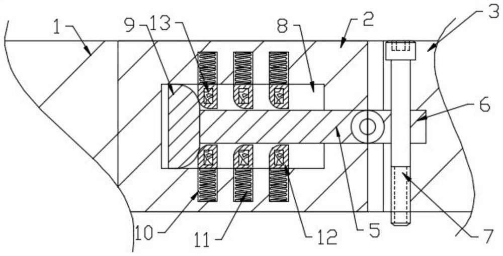
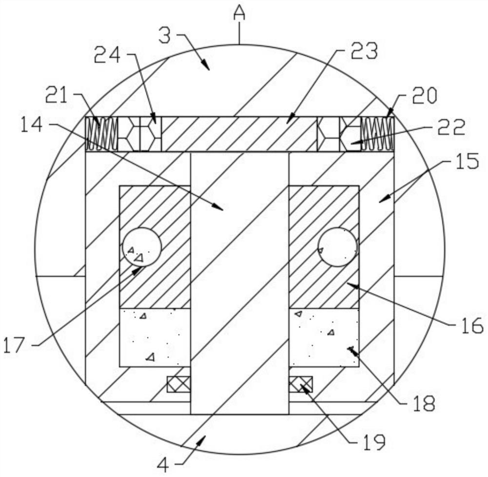
[0026] see Figure 1-5 , an anti-collision device for traffic engineering, comprising a plurality of uprights 1 fixedly connected to the ground, two side seats 2 are arranged at the upper and lower ends between two adjacent uprights 1, and two side seats 2 are provided with The connecting seat 3 is provided with a rotating roller 4 between the upper and lower connecting seats 3, the side seat 2 is fixedly connected with the column 1, the side seat 2 and the connecting seat 3 are connected through a connecting component, and the upper and lower ends of the rotating roller 4 are fixedly connected with Rotary column 14, the side end of the rotary column 14 is connected to the rotating seat 15, the rotating seat 15 is fixedly connected with the connecting seat 3, the first buffer assembly is arranged in the rotating seat 15, and the connecting seat 3 is provided with a block to prevent the rotation of the rotating column 14. The friction assembly, the roller 4 is provided with a n...

Embodiment 2

[0038] This embodiment makes further improvements on the basis of Embodiment 1, and the improvements are as follows: a third buffer assembly is provided between the moving block 27 and the slide plate 28, and the third buffer assembly includes a short column 32, a connecting cylinder 33, a connecting block 34 and the fourth spring 35, one end of the short post 32 is rotationally connected with the slide plate 28, the other end of the short post 32 is slidably connected with the connecting cylinder 33, the connecting cylinder 33 is rotationally connected with the moving block 27, and the short post 32 extends to one end of the connecting cylinder 33 to be fixed A connecting block 34 is connected, and the connecting cylinder 33 is connected with the connecting block 34 through a fourth spring 35. When the sliding plate 28 is subjected to an oblique impact, the sliding plate 28 moves so that the short column 32 fixedly connected with it slides in the connecting cylinder 33, and the...


PUM


Abstract

The invention discloses an anti-collision device for traffic engineering, and relates to the technical field of traffic engineering, wherein the anti-collision device comprises stand columns, side seats, connecting seats and a rotating roller; the side seats are fixedly connected with the stand columns, the side seats are connected with the connecting seats through connecting assemblies, the upper end and the lower end of the rotating roller are each provided with a rotating column, a rotating seat and a first buffer assembly, and a friction assembly is arranged in each connecting seat; and a plurality of second buffer assemblies are arranged in the rotating roller. The rotating roller containing a plurality of sliding plates is arranged between the stand columns to buffer impact, when the rotating roller is impacted, the sliding plates on the rotating roller are extruded to drive a connecting rod to move, then a moving block is extruded to move on the connecting column, buffer detection work is conducted through a third spring fixedly connected with the moving block, and when the rotating roller is impacted, the rotating roller rotates, so that the four sliding plates on the rotating roller rotate along with the rotating roller, and buffering work is continuously carried out.

Description

technical field [0001] The invention relates to the technical field of traffic engineering, in particular to an anti-collision device for traffic engineering. Background technique [0002] The anti-collision device is a very common road traffic safety device. It is widely used in some dangerous areas, such as road turns, exits and entrances, and roads with fast speeds. It is very Necessary traffic safety infrastructure. At the same time, the anti-collision device is also a safety device installed parallel to the road on both sides of the road or in the central divider, which can prevent abnormal driving vehicles from crossing the road due to driver error or other reasons. Or cross the central divider and break into the traffic accident of the opposite lane, protect the safety of roadside pedestrians, buildings, car drivers and occupants, and at the same time, it can induce the driver's sight, increase driving safety and beautify the road environment. Anti-collision devices ...

Claims


Application Information

Patent Timeline
Patent Type & Authority Applications(China)
IPC IPC(8): E01F15/04E01F15/00
CPCE01F15/0438E01F15/0484E01F15/0476E01F15/00
Inventor 李建立石凯王玉清李佳奇王巍石超
Owner 石凯
Features
  • Generate Ideas
  • Intellectual Property
  • Life Sciences
  • Materials
  • Tech Scout
  • Unparalleled Data Quality
  • Higher Quality Content
  • 60% Fewer Hallucinations
Learn More