
Bidirectional laminated slab dense splicing strong seam construction process and structure

A technology of laminated boards and dense joints, which is applied in the direction of building structures, floor slabs, building components, etc., can solve problems such as tear damage, weak laminated surfaces, disengagement, etc., and achieve the effect of enhancing integrity and preventing tear damage

Pending Publication Date: 2021-06-08
重庆中科建筑科技(集团)有限公司
View PDF9 Cites 0 Cited by
  • Summary
  • Abstract
  • Description
  • Claims
  • Application Information

AI Technical Summary

Problems solved by technology

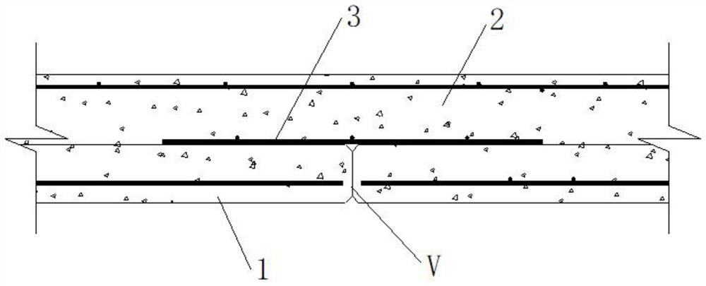
The problem with this method is that the natural rough surface is used to connect the prefabricated slab and the cast-in-place concrete. If the bonding force of the new and old concrete is not enough, it will be separated along the superimposed surface, and tear damage will occur.
And because the anchorage strength of the additional reinforcement is low, the additional reinforcement tends to slip
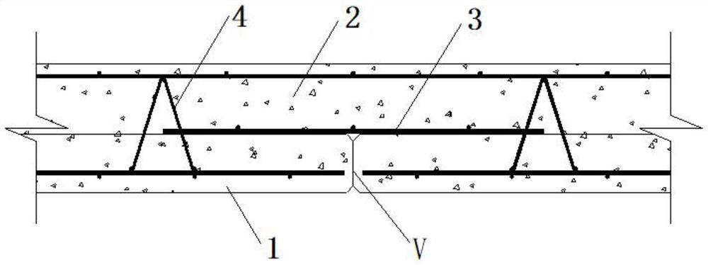
[0004] In "Construction of Prefabricated Concrete Structure Connection Nodes" 15G310-1, although the truss reinforcement 4 is added to the superimposed surface of the prefabricated slab 1 and the cast-in-place layer 2, such as figure 2 shown, but the superimposed surface near the seam V is still a weak point

Method used


Image

  • Bidirectional laminated slab dense splicing strong seam construction process and structure
  • Bidirectional laminated slab dense splicing strong seam construction process and structure
  • Bidirectional laminated slab dense splicing strong seam construction process and structure

Examples


no. 1 example

[0040] A construction technique for two-way laminated slab close-fitting strong joints, step (1) first laying the bottom plate connecting bars along the horizontal direction, laying the bottom plate reinforcing bars along the longitudinal direction, stacking the bottom plate reinforcing bars and the bottom plate connecting bars and binding them into the bottom plate reinforcement mesh, the bottom plate reinforcement mesh It is laid in the prefabricated slab template; the two ends of the bottom slab steel bars are bent upwards and protrude from the poured prefabricated slab surface, so that it can extend into the cast-in-place layer to enhance the integrity and safety of the structure and effectively prevent joints Larger cracks are generated along the superimposed surface, and then the tear damage occurs; finally, the truss reinforcement and suspension bars are placed on the bottom slab reinforcement mesh.

[0041] Step (2) Pouring the prefabricated slabs and performing wet mai...

no. 2 example

[0049] A construction technique for two-way laminated slab close-fitting strong joints, step (1) first laying the bottom plate connecting bars along the horizontal direction, laying the bottom plate reinforcing bars along the longitudinal direction, stacking the bottom plate reinforcing bars and the bottom plate connecting bars and binding them into the bottom plate reinforcement mesh, the bottom plate reinforcement mesh It is laid in the prefabricated slab template; the two ends of the bottom slab steel bars are bent upwards and protrude from the poured prefabricated slab surface, so that it can extend into the cast-in-place layer to enhance the integrity and safety of the structure and effectively prevent joints Larger cracks are generated along the superimposed surface, and then the tear damage occurs; finally, the truss reinforcement and suspension bars are placed on the bottom slab reinforcement mesh.

[0050] Step (2) Pouring the prefabricated slabs and performing wet mai...

no. 3 example

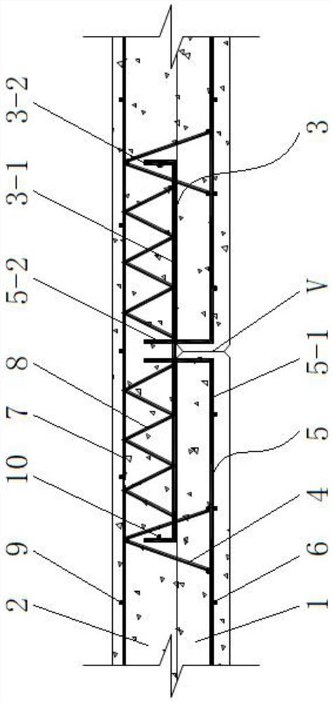
[0057] Such as image 3 As shown, a two-way laminated slab dense joint strong joint structure includes a prefabricated slab 1 and a cast-in-place layer 2. After the prefabricated slab 1 is mirror-symmetrically spliced, the cast-in-place layer 2 is poured on the prefabricated slab 1 . The prefabricated slab 1 is provided with bottom plate steel bars 5 laid longitudinally and bottom plate connecting bars 6 laid horizontally, and the bottom plate steel bars 5 and the bottom plate connecting bars 6 are fixed into a bottom plate reinforcement mesh by binding. The truss reinforcement 4 is laid horizontally on the reinforcement mesh of the bottom slab. The end of the base plate reinforcement 5 near the joint V of the prefabricated panel 1 is bent upwards by 90°, the horizontal section is the base plate stress reinforcement 5-1, and the vertical section is the base plate fixing reinforcement 5-2. The bottom plate fixing steel bar 5-2 passes through the prefabricated slab 1 and extend...


PUM


Abstract

The invention discloses a bidirectional laminated slab dense splicing strong seam structure. The bidirectional laminated slab dense splicing strong seam structure comprises a prefabricated slab and a cast-in-place layer, wherein bottom plate steel bars and bottom plate connecting bars are arranged in the prefabricated slab, the bottom plate steel bars comprise bottom plate load-bearing steel bars and bottom plate fixing steel bars, the bottom plate fixing steel bars are close to a splicing seam of the prefabricated slab, bent upwards and extend out of the surface of the prefabricated slab, additional steel bars and top plate compression steel bars are longitudinally laid in the cast-in-place layer, every two adjacent additional steel bars are connected to one top plate compression steel bar through a connecting web bar, the additional steel bars are perpendicular to the abutted seam, additional fixing steel bars are further arranged at the two ends of the additional steel bars and arranged in the vertical direction, and top plate connecting ribs and the top plate compression steel bars are laid in the transverse direction and in an overlapped mode. The bidirectional laminated slab dense splicing strong seam construction structure is high in integrality and bearing capacity, and the stability of the laminated slab near the abutted seam is high.

Description

technical field [0001] The invention relates to a splicing process and structure of concrete laminated slabs, in particular to a construction process and structure of two-way laminated slabs close-jointed strong joints. Background technique [0002] As a good combination of prefabricated slabs and cast-in-place slabs, concrete composite slabs have been widely used in engineering practice. However, due to the existence of joints between prefabricated slabs, the development of concrete laminated slabs is restricted. In the existing split-joint laminated slabs, due to insufficient bonding force between the prefabricated slab and the cast-in-place concrete on the laminated surface, it is easy to tear and fail along the laminated surface at the joint. This sudden brittle failure has a serious impact on the stability of the structure. [0003] Article 6.6.5 of the "Technical Regulations for Prefabricated Concrete Structures" (JGJ1-2014) provides a schematic diagram of the struct...

Claims


Application Information

Patent Timeline
IPC IPC(8): E04B5/17E04G21/00
CPCE04B5/17E04G21/00
Inventor 蒋林杨波尹犟席菲菲程振宇钟东旭魏国俊潘延辉李春文
Owner 重庆中科建筑科技(集团)有限公司
Learn More