Stable new energy roof structure

A roof structure, new energy technology, applied in the support structure of photovoltaic modules, renewable energy integration, roofing using tile/slate tile, etc. Looseness and other problems occur, to achieve the effect of improving the utilization rate of the device, improving the flexibility of use, and improving the efficiency of use

Inactive Publication Date: 2021-06-08
诚信伟业科技有限公司
View PDF0 Cites 0 Cited by
  • Summary
  • Abstract
  • Description
  • Claims
  • Application Information

AI Technical Summary

Problems solved by technology

[0004] The purpose of the present invention is to provide a stable new energy roof structure to solve the problem that the new energy roof structure proposed in the above background technology does not have the necessary limit assistance for the parts in the device during use, so that the parts can work for a long time After that, it is easy to loosen, causing the parts to fall off, the device cannot work normally, and the angle adjustment of the parts in the device cannot be adjusted, which reduces the working efficiency of the device, makes the device unable to adapt to different working environments, and reduces the adaptation effect of the device. The liquid cannot be discharged uniformly, which makes the problem of liquid accumulation in the device prone to occur

Method used


Image

  • Stable new energy roof structure
  • Stable new energy roof structure
  • Stable new energy roof structure

Examples


Embodiment Construction

[0018] The following will clearly and completely describe the technical solutions in the embodiments of the present invention with reference to the accompanying drawings in the embodiments of the present invention. Obviously, the described embodiments are only some, not all, embodiments of the present invention. Based on the embodiments of the present invention, all other embodiments obtained by persons of ordinary skill in the art without making creative efforts belong to the protection scope of the present invention.

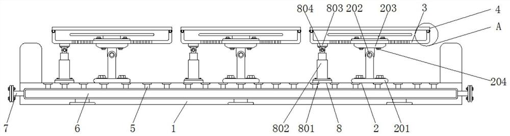
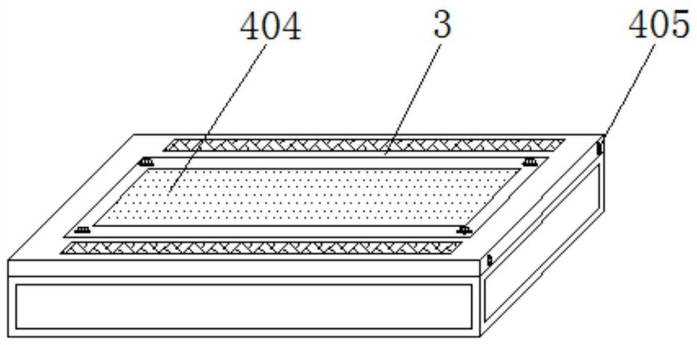
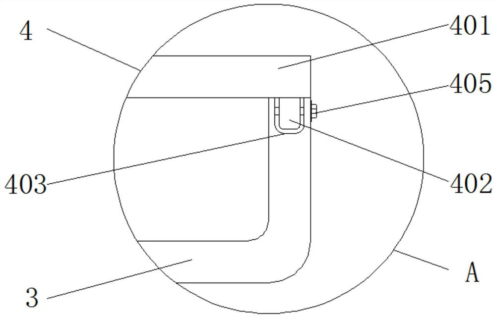
[0019] see Figure 1-3 , the present invention provides a technical solution: a stable new energy roof structure, including a top platform 1 and a limit mechanism 4, the top of the top platform 1 is provided with a movable mechanism 2, and the top of the movable mechanism 2 is equipped with a working Frame 3, movable mechanism 2 includes support frame 201, rotating shaft 202, movable frame 203 and movable bolt 204, the outer wall of support frame 201 is provid...


PUM


Abstract

The invention discloses a stable new energy roof structure. The stable new energy roof structure comprises a top table and a limiting mechanism; a movable mechanism is movably arranged at the top of the top table, and a working frame is movably arranged at the top of the movable mechanism; the limiting mechanism is movably connected to the top of the working frame, and a liquid leakage pipe is arranged on the inner side of the outer wall of the top table; a liquid storage pipe is arranged at the bottom of the liquid leakage pipe; and a connector is arranged on the outer wall of the liquid storage pipe. The new energy roof structure is provided with the top table, and a supporting frame is vertically arranged on the outer wall of the top table, so that when the supporting frame works on the device, the corresponding vertical state can be kept all the time, the situation that the use stability of parts borne on the supporting frame is affected due to unnecessary shaking after the supporting frame works for a long time is prevented, the use efficiency of the device is improved, meanwhile, the supporting frame and the movable frame form a rotating structure through a rotating shaft, and when a user needs to adjust the working angle of the parts in the device, the supporting frame and the movable frame can conduct angle adjustment through the effect of the rotating shaft.

Description

technical field [0001] The invention relates to the technical field of new energy roof structures, in particular to a stable new energy roof structure. Background technique [0002] New energy, also known as unconventional energy, refers to various forms of energy other than traditional energy, and refers to energy that has just begun to be developed and utilized or is being actively researched and is yet to be promoted, such as solar energy, geothermal energy, wind energy, ocean energy, and biomass energy. And nuclear fusion energy, etc., new energy application houses are houses that use new energy as electricity. The roof needs to use solar panels for energy absorption assistance. A solar roof is to install solar power generation devices on the top of the house, using solar photovoltaic technology Power generation is carried out in the urban and rural building fields to achieve the goal of energy conservation and emission reduction, and to improve the use effect of new ene...

Claims


Application Information

Patent Timeline
Patent Type & Authority Applications(China)
IPC IPC(8): E04D13/00E04D13/18F24S30/425F24S25/65F24S25/63F24S25/61H02S20/30
CPCE04D13/00F24S25/61F24S25/63F24S25/65F24S30/425H02S20/30Y02B10/10Y02B10/20Y02E10/47Y02E10/50
Inventor 张玉
Owner 诚信伟业科技有限公司
Why Eureka
Try Eureka