

Electric equipment for film coating
A technology of electrical equipment and the main body, which is applied in the field of coating electrical equipment, can solve problems such as easy loosening of internal parts, lower device use efficiency, and lack of positioning assistance for parts in the device, so as to improve the flexibility of use and improve the quality of use. Safety and improvement of maintenance timeliness
- Summary
- Abstract
- Description
- Claims
- Application Information
AI Technical Summary
Problems solved by technology
Method used
Image

Examples
Embodiment Construction
[0018] The following will clearly and completely describe the technical solutions in the embodiments of the present invention with reference to the accompanying drawings in the embodiments of the present invention. Obviously, the described embodiments are only some, not all, embodiments of the present invention. Based on the embodiments of the present invention, all other embodiments obtained by persons of ordinary skill in the art without making creative efforts belong to the protection scope of the present invention.
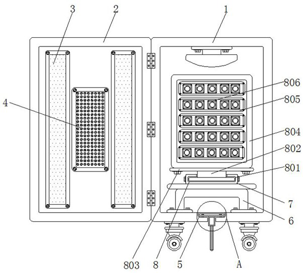
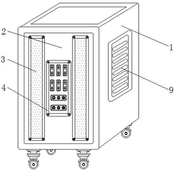
[0019] see Figure 1-3 , the present invention provides a technical solution: a kind of electrical equipment for coating, including a main body 1 and a movable plate 4, a shell plate 2 is movably arranged on the left side of the outer wall of the main body 1, and a window 3 is movably arranged on the inner side of the outer wall of the shell plate 2, The movable plate 4 is movably arranged on one side of the outer wall of the window 3, the bottom of the main b...
PUM
 Abstract
Description
Claims
Application Information