Fan control method and system, terminal equipment and storage medium

A fan control and fan technology, applied in pump control, mechanical equipment, engine control, etc., can solve the problems of user manual operation control, fixed single fan working mode, unable to meet the user's demand for smart home equipment, etc., to achieve intelligent control mode , the effect of improving experience

Pending Publication Date: 2021-06-08
FOSHAN VIOMI ELECTRICAL TECH +1
View PDF12 Cites 1 Cited by
  • Summary
  • Abstract
  • Description
  • Claims
  • Application Information

AI Technical Summary

Problems solved by technology

Therefore, the existing fan not only has a fixed and single working mode, but also requires manual operation and control by the user. It can be seen that the interactive mode of the existing fan cannot meet the user's needs for smart home devices.

Method used


Image

  • Fan control method and system, terminal equipment and storage medium
  • Fan control method and system, terminal equipment and storage medium
  • Fan control method and system, terminal equipment and storage medium

Examples


Embodiment Construction

[0030] The technical solutions in the embodiments of the present application will be clearly and completely described below in conjunction with the drawings in the embodiments of the present application. Obviously, the described embodiments are part of the embodiments of the present application, not all of them. Based on the embodiments in this application, all other embodiments obtained by persons of ordinary skill in the art without making creative efforts belong to the scope of protection of this application.

[0031] The flow charts shown in the drawings are just illustrations, and do not necessarily include all contents and operations / steps, nor must they be performed in the order described. For example, some operations / steps can be decomposed, combined or partly combined, so the actual order of execution may be changed according to the actual situation.

[0032] It should be understood that the terms used in the specification of this application are for the purpose of de...


PUM


Abstract

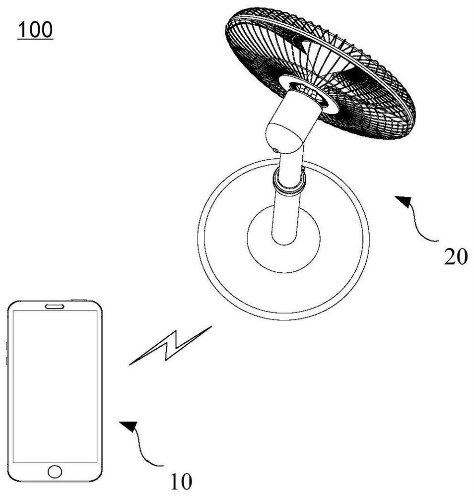
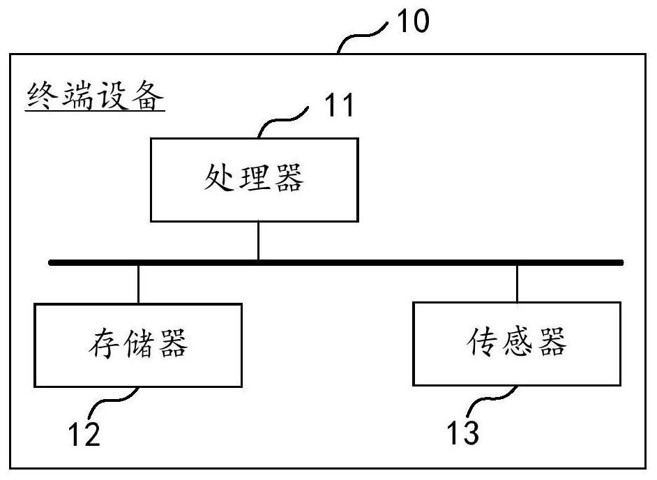
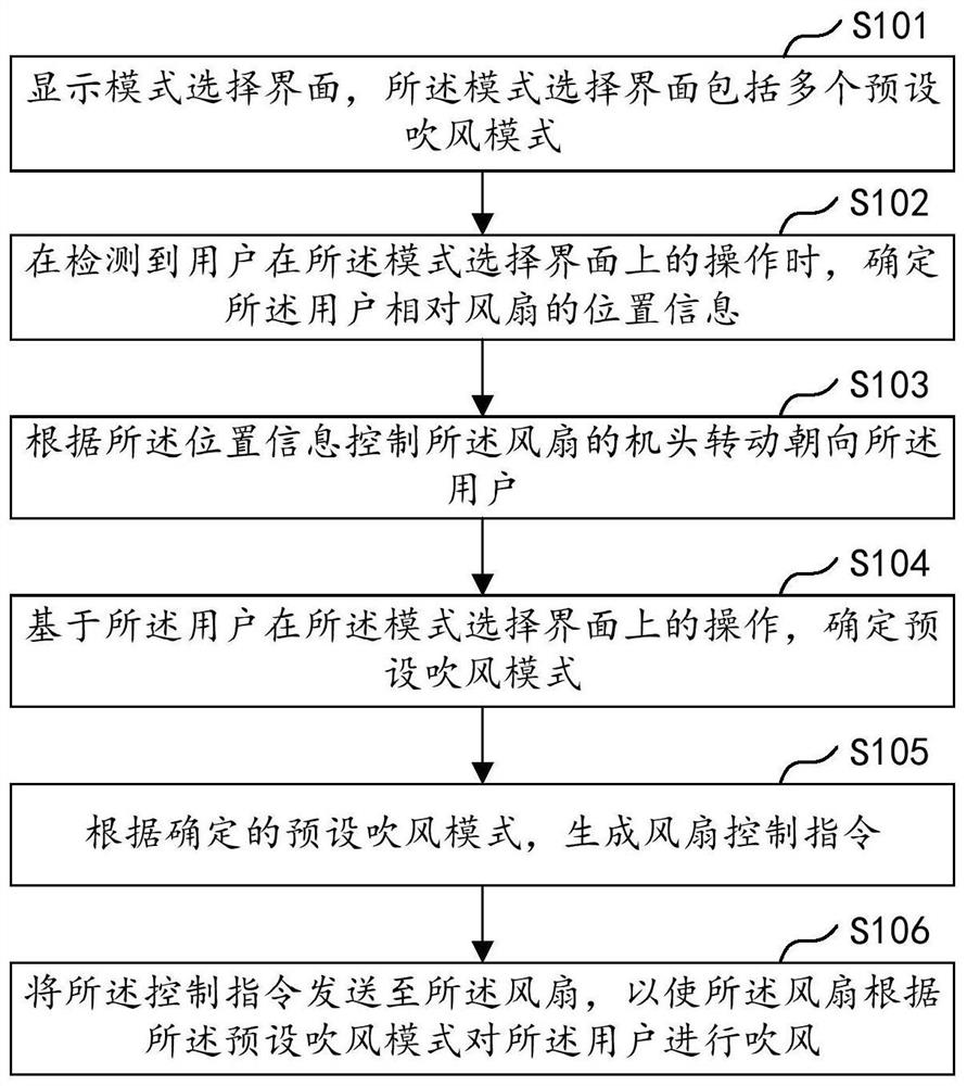
The invention provides a fan control method and system, terminal equipment and a storage medium. The method comprises the steps of: displaying a mode selection interface, wherein the mode selection interface comprises a plurality of preset blowing modes; when operation of a user on the mode selection interface is detected, determining position information of the user relative to a fan; controlling a machine head of the fan to rotate towards the user according to the position information; determining a preset blowing mode based on the operation of the user on the mode selection interface; generating a fan control instruction according to the determined preset blowing mode; and sending the control instruction to the fan, so as to enable the fan to blow air to the user according to the preset blowing mode. Therefore, the user experience is improved.

Description

technical field [0001] The present application relates to the technical field of smart home, and in particular to a fan control method, terminal equipment, control system and storage medium. Background technique [0002] At present, the fans on the market all adopt a directional blowing mode or a oscillating blowing mode within a fixed range, and both the directional blowing mode and the oscillating blowing mode need to be manually turned on by the user. For example, the user presses a gear button, and the fan performs fixed air supply according to the gear corresponding to the gear button; or the user presses the swing button on the head of the fan, and the fan starts to swing and blow air. Therefore, the existing fan not only has a fixed and single working mode, but also requires manual operation and control by the user. It can be seen that the interactive mode of the existing fan cannot meet the user's demand for smart home devices. Contents of the invention [0003] T...

Claims


Application Information

Patent Timeline
Patent Type & Authority Applications(China)
IPC IPC(8): F04D27/00
CPCF04D27/00F05D2270/804
Inventor 陈小平唐清生
Owner FOSHAN VIOMI ELECTRICAL TECH
Why Eureka
Try Eureka